You are using an out of date browser. It may not display this or other websites correctly.
You should upgrade or use an alternative browser.
You should upgrade or use an alternative browser.
Y-Wing (Gold Leader) Build - Nice-N Model Designs
- Thread starter Corellianexports
- Start date
Since I already marked the holes in the side of the main fuselage, I decided to take a break from all the structural stuff and move on to the electronics. Here's how every thing lines up with the hole and where the wires will go:
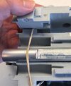
A 1/8" drill bit fits perfectly within the hole that runs through the pipe, so I'm going with a 1/8" hole:
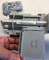
I have some small wire left over from my full size R2 logic boxes, so I'll just use that here. They're easy to bend and small enough to fit in the hole:
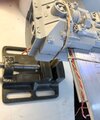
With the wing in place, the hole with the wires is completely covered up, so we're in good shape:
While going through my grab bag of electronic stuff, I came across some thing I found at the Dollar store:
I won't use this lighting system for this project, but I think it would be a great way of adding some great details to a Y-Wing or X-Wing without spending a lot of money or time on it.
Based on what I had, the best power source to go with was either 1.5v or 3v due to the voltage and amperage on my switches and battery holders, but I discovered that 1.5v barely lights up my LEDs with or without a resistor. I couldn't find a 3v batteries that would fit in my battery holder, but I did find several small 12v batteries that I have no need for (left over from my R2 projects). Unfortunately, there's a chance the battery will fry my switch and/or holder, but when it comes to electronics it's usually a "try it" situation, and since the 12v battery is really small, I tried it and sure enough, it worked:
A basic, medium size, red LED:
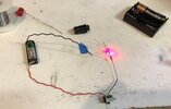
Jumbo size, red LED:
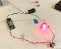
Jumbo size, super bright, white LED:
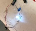
Using the push button switch, instead:
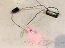
The resistor did get a little hot, but I think this set up will do:
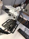

A 1/8" drill bit fits perfectly within the hole that runs through the pipe, so I'm going with a 1/8" hole:

I have some small wire left over from my full size R2 logic boxes, so I'll just use that here. They're easy to bend and small enough to fit in the hole:

With the wing in place, the hole with the wires is completely covered up, so we're in good shape:

While going through my grab bag of electronic stuff, I came across some thing I found at the Dollar store:
I won't use this lighting system for this project, but I think it would be a great way of adding some great details to a Y-Wing or X-Wing without spending a lot of money or time on it.
Based on what I had, the best power source to go with was either 1.5v or 3v due to the voltage and amperage on my switches and battery holders, but I discovered that 1.5v barely lights up my LEDs with or without a resistor. I couldn't find a 3v batteries that would fit in my battery holder, but I did find several small 12v batteries that I have no need for (left over from my R2 projects). Unfortunately, there's a chance the battery will fry my switch and/or holder, but when it comes to electronics it's usually a "try it" situation, and since the 12v battery is really small, I tried it and sure enough, it worked:
A basic, medium size, red LED:

Jumbo size, red LED:

Jumbo size, super bright, white LED:

Using the push button switch, instead:

The resistor did get a little hot, but I think this set up will do:

Last edited:
After giving it some more thought, I realized that the push button switch won't work because if it should go bad in the future, it will be very difficult to remove without ruining the wires and possibly breaking something, so I decided to go with the surface switch that can simply be bolted in place. I used the same switch on my SS TIE fighter, full scale R2 and R5 domes. All of those setups use LEDs with either 9v or 3v batteries.
I use some X-Acto knives and a square file to create an indentation at the bottom of one of the "battery" holes so that the switch can be easily bolted:
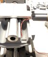
With switch installed:
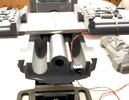
And with the cover in place, the switch just fits:
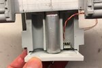
Up next, fitting the right size LEDs into the engines, engine assembly and then back to the aluminum structure.
I use some X-Acto knives and a square file to create an indentation at the bottom of one of the "battery" holes so that the switch can be easily bolted:

With switch installed:

And with the cover in place, the switch just fits:

Up next, fitting the right size LEDs into the engines, engine assembly and then back to the aluminum structure.
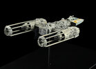
While researching the engine lights, I came across some nice photos of the ROTJ version of the Y-Wing which appears to have the same paint scheme as the MR version of the Y-Wing:
As for the engine lights, they simply filled the engine tube with a large bulb:
This is best photo I've seen so far of just the engine. It looks like only the center hole is colored red. The area surrounding the central tube is white and the area behind the heat sink is black:
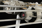
It does look like the X-Wing engines are completely red behind the heat sinks in this screen cap, however:

i did some additional research, including watching the end of ESB and I came to the conclusion that the entire engine is more than likely lit up just like the X-Wing engines. I definitely do some testing once everything is assembled.
As for the engine lights, they simply filled the engine tube with a large bulb:

This is best photo I've seen so far of just the engine. It looks like only the center hole is colored red. The area surrounding the central tube is white and the area behind the heat sink is black:

It does look like the X-Wing engines are completely red behind the heat sinks in this screen cap, however:

i did some additional research, including watching the end of ESB and I came to the conclusion that the entire engine is more than likely lit up just like the X-Wing engines. I definitely do some testing once everything is assembled.
Last edited:
In order to complete the electronics, I decided to put together the engines. Here’s the main parts:
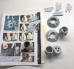
What’s missing are a couple of tubes (and a few other parts that I'll list at the bottom of this post) that hold the heat sinks and behind those, the lights.
I looked at the tubes at Plastruct (TB-28) and unfortunately there’s a $25 minimum to place an order so I looked at some alternatives including some aluminum tubes. My only concern with aluminum is that it might be too heavy unless it is attached to the aluminum structure. After checking the instructions I made an interesting discovery:
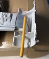
There is a hole within the engines where any tubing (7/8”) fits perfectly and intersects with the aluminum structure, so it is possible to connect the tubes.
Considering the amount of foresight the ILM modelers gave to lighting, I wouldn’t be surprised if an aluminum or steel tube was planned for holding some lights in order to avoid melting any plastic.
The parts are cleaned up and I use an artists saw the cut out the fins for the engines:
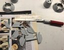
I use some 220 and the largest gritt I had from the dollar store to start cleaning up the bottoms of the cone parts:
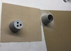
Here are all the parts cleaned up and done:
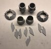
A list of parts that are needed to complete the engines (add them to your shopping list):
White Plastic Tubing (or aluminum): 7/8" OD, 3/4" ID, 2 3/4" Long (2x)
7/8" clear plastic discs (2x)
3/4" clear plastic discs (2x)
Plastic Rings (white or clear): 1 1/32 or 1/16" OD, 7/8" ID, (4x or 6x)
For the engine "vents":
Plastic Rings (white or clear): 1.5" OD, 1 5/16" ID (Thickness is 1/16"), 3/32" Long (2X)

What’s missing are a couple of tubes (and a few other parts that I'll list at the bottom of this post) that hold the heat sinks and behind those, the lights.
I looked at the tubes at Plastruct (TB-28) and unfortunately there’s a $25 minimum to place an order so I looked at some alternatives including some aluminum tubes. My only concern with aluminum is that it might be too heavy unless it is attached to the aluminum structure. After checking the instructions I made an interesting discovery:

There is a hole within the engines where any tubing (7/8”) fits perfectly and intersects with the aluminum structure, so it is possible to connect the tubes.
Considering the amount of foresight the ILM modelers gave to lighting, I wouldn’t be surprised if an aluminum or steel tube was planned for holding some lights in order to avoid melting any plastic.
The parts are cleaned up and I use an artists saw the cut out the fins for the engines:

I use some 220 and the largest gritt I had from the dollar store to start cleaning up the bottoms of the cone parts:

Here are all the parts cleaned up and done:

A list of parts that are needed to complete the engines (add them to your shopping list):
White Plastic Tubing (or aluminum): 7/8" OD, 3/4" ID, 2 3/4" Long (2x)
7/8" clear plastic discs (2x)
3/4" clear plastic discs (2x)
Plastic Rings (white or clear): 1 1/32 or 1/16" OD, 7/8" ID, (4x or 6x)
For the engine "vents":
Plastic Rings (white or clear): 1.5" OD, 1 5/16" ID (Thickness is 1/16"), 3/32" Long (2X)
Last edited:
That’s a great idea.
So today I am cleaning up the engine fins:
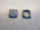
I use a x-acto knife to clean up the ends and then the usual sandpaper to make sure that they are flat:
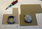
I filled in some small, bubble holes on the back with standard, modelers putty:
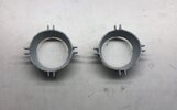
While cleaning up the fins with a small x-acto knife, one of them came loose, so I used some super glue to put it back in place.
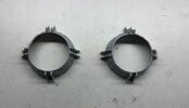
Here's the finished products:
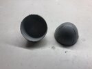
I discovered a crack in one of the Leggs domes, so again I used a few drops of super glue and then some painters tape with a rubber band to hold it in place:
So today I am cleaning up the engine fins:

I use a x-acto knife to clean up the ends and then the usual sandpaper to make sure that they are flat:

I filled in some small, bubble holes on the back with standard, modelers putty:

While cleaning up the fins with a small x-acto knife, one of them came loose, so I used some super glue to put it back in place.
Here's the finished products:

I discovered a crack in one of the Leggs domes, so again I used a few drops of super glue and then some painters tape with a rubber band to hold it in place:

Last edited:
Now on to the center "fins". Here they are, untouched:
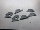
I use an artists saw and a pair of wire cutters, or "nippers" to remove the sprue. The key is to work around the part as much as possible before cutting close to the edge. It's a lot like carving wood:
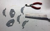
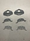
While I'm cleaning up a couple of the fins, I realized that they were suppose to be for the Red Jammer version of the Y-Wing, so I replace them with the correct parts for Gold Leader. This version has a sort of chain link fence pattern to it. Here's the finished parts:
Next week, more cleaning up, machining the tubes for the engines, electronics and the possibility of "lightening" the fuselage.

I use an artists saw and a pair of wire cutters, or "nippers" to remove the sprue. The key is to work around the part as much as possible before cutting close to the edge. It's a lot like carving wood:

While I'm cleaning up a couple of the fins, I realized that they were suppose to be for the Red Jammer version of the Y-Wing, so I replace them with the correct parts for Gold Leader. This version has a sort of chain link fence pattern to it. Here's the finished parts:

Next week, more cleaning up, machining the tubes for the engines, electronics and the possibility of "lightening" the fuselage.
Last edited:
Last night I noticed some large pour stubs near the ends of the engine halves and realized that using a dremel would be the best way to remove them. Of course the bad news about the dremel is that it sends resin material every where, so the best place to use it is out side.
Due to some bad weather coming in tomorrow and through the rest of this week, I decided to get a head start on dremeling the engines:
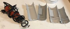
And here they are, cleaned up:
Due to some bad weather coming in tomorrow and through the rest of this week, I decided to get a head start on dremeling the engines:

And here they are, cleaned up:

Unfortunately, there isn’t more on those instructions.watching and learning from your build, as I now have in my possession the same kit...
Your share of the instructions is very much welcome, but they seem to be missing anything after page 13
Do you have anything more past this page?
When I built my Gold Leader a few years ago, I had to pour over reference pics to find locations of many of the smaller plant on parts. Piping too.
I think my eyes were crossed for months afterwards. Lol
The instructions will guide you for the major parts of GL, but you’re on your own for the rest.
You're referring to the Gold Y-Wing instructions. If you use the Red Y-Wing instructions, you'll find more information beyond page 13, although the details are a little different here and there.watching and learning from your build, as I now have in my possession the same kit...
Your share of the instructions is very much welcome, but they seem to be missing anything after page 13
Do you have anything more past this page?
One reason why I will be documenting my build, completely from start to finish is because the Gold Y-Wing instructions are incomplete.
Also, the kit itself is incomplete, so I might offer an "extension" kit in the future. It will depend on how this build goes.
Chuffy 70
Active Member
any idea where I might find those, a bit green to this whole SScale m'larkyYou're referring to the Gold Y-Wing instructions. If you use the Red Y-Wing instructions, you'll find more information beyond page 13, although the details are a little different here and there.
One reason why I will be documenting my build, completely from start to finish is because the Gold Y-Wing instructions are incomplete.
Also, the kit itself is incomplete, so I might offer an "extension" kit in the future. It will depend on how this build goes.
The Red Y-Wing instructions do not appear to be available online any more, so I'm going to try and attach them here.any idea where I might find those, a bit green to this whole SScale m'larky
Attachments
Chuffy 70
Active Member
That's fantastic, just what I was looking for...can't thank you enough, the support on RPF is truly wonderful. Thank youThe Red Y-Wing instructions do not appear to be available online any more, so I'm going to try and attach them here.
You're referring to the Gold Y-Wing instructions. If you use the Red Y-Wing instructions, you'll find more information beyond page 13, although the details are a little different here and there.
One reason why I will be documenting my build, completely from start to finish is because the Gold Y-Wing instructions are incomplete.
Also, the kit itself is incomplete, so I might offer an "extension" kit in the future. It will depend on how this build goes.
Thank you so much! It's been frustrating how the instructions just trail off without being completed. The same thing happened with the X-wing.
dep974
New Member
Hi..it seems that you are reversed the right side and back side of the wings....Oups...Sorry it has been corrected........I discover more problems. Nothing appears to be lining up correctly. Apparently, I had been scratching my head last weekend over more than just the two main sections not lining up properly. And in order to glue the two main sections together, the wings have to assemble properly and of course, they don't.
So here's the left side wing before attaching it to the main section:
View attachment 1355515
Here it attached:
View attachment 1355516
The idea (according to the instructions) is to insert the wing just under the slot, above the aluminum.
Unfortunately, there isn't enough room for the wing and the aluminum. Here's the other side:
View attachment 1355517
View attachment 1355518
Flipped over, here is the bottom of the right side wing:
View attachment 1355519
Bottom of the left side wing:
View attachment 1355520
Looking at it from the front, the top section is being pushed up:
View attachment 1355521
The reason is that the two, resin wedges are too high:
View attachment 1355522
About 1/16" of material needs to be removed on both sides:
View attachment 1355523
Sanding them down will take a long time, so I simply machine them down using the mill. There's one problem solved. Next up is the second problem with the wings.
Last edited:
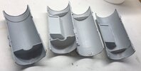
This week I decided to continue to clean up parts so that they're ready for pre-assembly. I'm going to continue with the large, engine pieces:
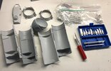
The domes had to be trimmed right down to the edge because they will fit over the main engine parts. I'll sand them down later:
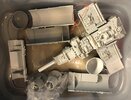
Now onto the small parts, including these little goodies on the right:
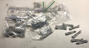
These engine details are fairly important because they appear near the front of the model and are very visual, so we want to keep as much detail as possible. Unfortunately, they contain lots of little details that are very difficult to cast, so be cautious while cleaning these up. I made the mistake of not using my reference photos before cleaning them and I removed some detail from the ends (although most of the detail disappeared due to the pour spout). The good news is that the detail is just a flat, step so it can be put back with a little modelers putty.
So here they are, cleaned up with the smallest x-acto knife I have:
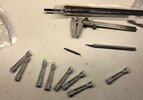
The parts should have a rectangular indentation for the ABS Tee, but this area is completely filled in with resin from the casting. I scratched my head for a while on this one because this area can be removed, slowly with an x-acto knife, but it won't be a perfect rectangle. It's also a dangerous process, so I checked my stash of end mills and pulled the smallest one I had, which I believe is 1/8" in diameter. I checked the size against the part and sure enough, it will work.
It turns out that the part is strong enough to stay in place within the clamp without breaking. I mill each part with two passes:
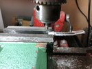
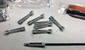
Here they are with the Tee:
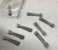
I clean them up a little with an x-acto knife and then apply some putty to put back the small "step" on the back of each one:

The domes had to be trimmed right down to the edge because they will fit over the main engine parts. I'll sand them down later:

Now onto the small parts, including these little goodies on the right:

These engine details are fairly important because they appear near the front of the model and are very visual, so we want to keep as much detail as possible. Unfortunately, they contain lots of little details that are very difficult to cast, so be cautious while cleaning these up. I made the mistake of not using my reference photos before cleaning them and I removed some detail from the ends (although most of the detail disappeared due to the pour spout). The good news is that the detail is just a flat, step so it can be put back with a little modelers putty.
So here they are, cleaned up with the smallest x-acto knife I have:

The parts should have a rectangular indentation for the ABS Tee, but this area is completely filled in with resin from the casting. I scratched my head for a while on this one because this area can be removed, slowly with an x-acto knife, but it won't be a perfect rectangle. It's also a dangerous process, so I checked my stash of end mills and pulled the smallest one I had, which I believe is 1/8" in diameter. I checked the size against the part and sure enough, it will work.
It turns out that the part is strong enough to stay in place within the clamp without breaking. I mill each part with two passes:

Here they are with the Tee:

I clean them up a little with an x-acto knife and then apply some putty to put back the small "step" on the back of each one:

Last edited:
Similar threads
- Sale
- Replies
- 6
- Views
- 706
- Replies
- 5
- Views
- 1,603
