You are using an out of date browser. It may not display this or other websites correctly.
You should upgrade or use an alternative browser.
You should upgrade or use an alternative browser.
xl97's Iron Man motorized face plate tutorial
- Thread starter xl97
- Start date
Oh ok well if I use exactly the same thing as you can I take a chance go straight away on the mini or the uno stage is really important because for ne it wil probably decide If I do the electronic now or wait after my birthday to get some money to be able to buy it because I have around 200 $ remaining and I didnt bought bondo yet and the paint I will use cost around 15 $ per can for sure I would love to have electronic for this year montreal comic con but if its really important then I will onky do led eyes for now and wait for next year for the face plate because as we say . Better wait and make it awesome than go fast and ruin all
Envoyé de mon SM-G530W en utilisant Tapatalk
Envoyé de mon SM-G530W en utilisant Tapatalk


1.) did you meter/check that you are getting +5v from your module?
2.) add a wire from Arduino GND pin to the GND rail on breadboard... see if that helps with jitter.
I think I did the test for the module. Will double check tonight. And work on add the wire. Since there are GND on both Power section and Digital section on the R3 board. May I ask which GND pin should I connect on the Arduino board?
Thanks
Dio
Yeah same ahah price are not on the canadian propsmaker side right nowEverything is so cheap in States. Wish I can live there.
xl97
Master Member
I order from China. (ebay). = cheap.
Long wait for shipping.. but cheap.
* I use a CP2102 based programmer:
http://www.ebay.com/itm/1pcs-6Pin-U...504639?hash=item33ae4b54ff:g:ViAAAOSwsB9WCNWw
install drivers.. temporarily connect the headers to the pro-mini and upload through the IDE like you normally do.
I have used and made the other version you posted an image of.. I had to manually reset the board (reset button) at certain time to get it to upload.. (its a PAIN when the other ones work fine and cost a couple bucks).. if you HAVE an extra cable laying around and want to use.. it will work. (just have to press the button on each upload)
get both if you can afford it.. prototyping on a UNO is much easier..
get them off ebay..
pro-mini costs roughly $3.00 USD
uno maybe like $6.00 USD
when is comic con?
your biggest cost will be the batteries and servos IMHO.. the rest is just a few dollars here and there..
Dio
it doesnt matter what GND pin you use on the UNO.. they are all the same I believe.
but it 'looks' that the grounds going to breadboard/servo is -not- connected to the GND going to UNO from battery..
and since the GND (output) from the +5 module is the only GND going to servos/breadboard... its 'seems' as if they dont know about each other more or less.
to 'me' it looks as if the battery GND is going to UNO (hence through its regulator)...
another GND wire from the battery is going to the +5 module thing..
there is a (now regulated) GND output wire coming FROM the +5 module thingy to the servo/breadboard...
put a wire in a GND pin on the UNO.. and connect it to the GND rail on he breadboard that the leds,/servos//etc all connect to.
that should stop your servo jitter.
Last edited by a moderator:
xl97
Master Member
I'd say doable.. but you better get to ordering... LOL
China takes WEEKS..
make a list:
Arduino Pro-Mini
CP2102 programmer (for Pro-Mini)
Arduino Uno.. (I prefer the one with the DIP Atmega328 chip.. not the SMD one)
pack of assorted resistors
pack of assorted capacitors
pack of leds
pack of jumper wires for prototyping on breadboard..
battery source (I recommend using +7.4v Li-Ion packs.. or Li-Po packs) (get wahtever works best for your project and intended placement.
^ the battery source will dictate A LOT of what resistors/caps..etc will be used (values..etc)
servos.. smallest, strongest you can find and afford.. (Hobby King has A TON of info on servos).. once you find the model you want.. order it form the cheapest source I guess.

I order from China. (ebay). = cheap.
Long wait for shipping.. but cheap.
* I use a CP2102 based programmer:
http://www.ebay.com/itm/1pcs-6Pin-U...504639?hash=item33ae4b54ff:g:ViAAAOSwsB9WCNWw
install drivers.. temporarily connect the headers to the pro-mini and upload through the IDE like you normally do.
I have used and made the other version you posted an image of.. I had to manually reset the board (reset button) at certain time to get it to upload.. (its a PAIN when the other ones work fine and cost a couple bucks).. if you HAVE an extra cable laying around and want to use.. it will work. (just have to press the button on each upload)
get both if you can afford it.. prototyping on a UNO is much easier..
get them off ebay..
pro-mini costs roughly $3.00 USD
uno maybe like $6.00 USD
when is comic con?
your biggest cost will be the batteries and servos IMHO.. the rest is just a few dollars here and there..
@Dio
it doesnt matter what GND pin you use on the UNO.. they are all the same I believe.
but it 'looks' that the grounds going to breadboard/servo is -not- connected to the GND going to UNO from battery..
and since the GND (output) from the +5 module is the only GND going to servos/breadboard... its 'seems' as if they dont know about each other more or less.
to 'me' it looks as if the battery GND is going to UNO (hence through its regulator)...
another GND wire from the battery is going to the +5 module thing..
there is a (now regulated) GND output wire coming FROM the +5 module thingy to the servo/breadboard...
put a wire in a GND pin on the UNO.. and connect it to the GND rail on he breadboard that the leds,/servos//etc all connect to.
that should stop your servo jitter.
Sorry my bad, it should looks like this:

I'm working on the ground wire now. Will keep you posted.
Thanks
Dio

*Update:
opk I see the GND wire now..
but youre saying that adding breaks everything?
(but if you remove it works fine again?)
So after I add the GND wire. It looks like this:
When I push the button, there is no reaction like the light is not on. The servo is not moving to the right angle except jitter.
I'm wondering is that possible that my jumper wire is weak so make the power source unstable?
I did hook up two wire from the +/- on the breadboard. When I turn the power on. My meter showing around 4.83V so it dropped a bit from 4.98V. And every time when servo jitter, it drops a lot. The lowest could be 3.33V. Some time it showing 4.23V. it vary every time.
Last edited by a moderator:
Leylander
Well-Known Member
not sure how those work.
(but whatever works for you)
You can see it here:
https://www.youtube.com/watch?NR=1&v=4oEpHHu5Z18&feature=endscreen
I'm planning on doing the same thing. 3 servo system.
It uses 2 for the faceplate and one for the chin.
I took the liberty of cleaning up the wires a bit on the 123D circuits setup:

Still not ideal, but works for me. I'm still far from this stage, but I like to plan ahead
")
For this setup, the code needs an additional servo.
RocFoamArmory
Active Member
Quick question everyone. It's about arduino and LED issues. Has anyone tried wiring a motor driver such as the L298N H-bridge to drive high power leds?
xl97
Master Member
Do a search on the Arduino.cc forums.. (you'll find everything you need there)..
For the most part.. I have either used a transistor to control high powered leds.. or made a constant current driver..
re: the hinge system..
looks good if you want to go the route where you have the 'slots' for the hinge arms to go..(in the helmet)
so go that route.. some dont.
@Leylander
What diagram are you 'cleaning up'?
I dont think its get any more direct than this:
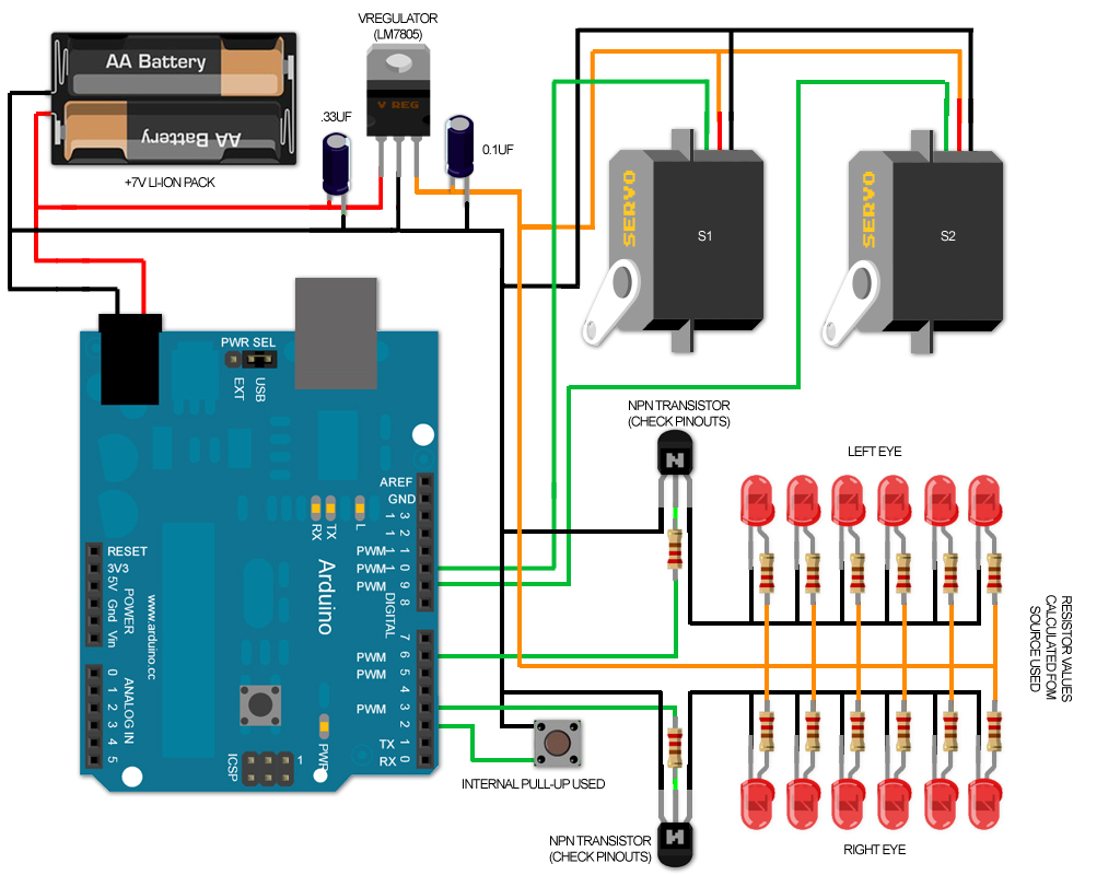
Similar threads
- Replies
- 1
- Views
- 1,121
- Replies
- 8
- Views
- 6,887
- Replies
- 1,606
- Views
- 499,879