I have an overall length for Red 3 of about 515mm (or 20 9/32").
Let me explain a little bit about how I'm getting my measurements. To take measurements from photographs, we ideally want the photographs, at the very least, to exhibit mathematical perspective. Mathematical perspective just means the same rules of perspective that artists use:
(the main difference being that an artist will generally draw a sphere with a more or less circular silhouette, whereas the true mathematical perspective projection - which, incidentally, is what you get if you take a picture with a pinhole camera and a flat image plane - can distort spheres into elongated egg shapes).
Photographs, however, typically exhibit a certain amount of lens distortion, most commonly noticed as "barrel distortion", where straight lines appear to bow outwards (telephoto lenses often exhibit a certain amount of "pincushion distortion", the opposite effect). As a rough rule of thumb, it's generally held that you can't totally eliminate lens distortion from photographs where the subject is less than about ten feet away.
Unfortunately, most of the x-wing pictures were taken from no more than a couple of feet away, and some from as close as four inches.
However, point and shoot digital cameras like the Coolpix 990 which was used to take many of the x-wing pictures have very small sensors, and lenses that are rather smaller than typical 35mm camera lenses. The Coolpix 990 sensor is just 7.18mm wide, compared to 36mm for a full frame of 35mm film, so we can essentially imagine the Coolpix 990 as being a one fifth scale model of a full size 35mm camera. In other words, a picture taken with the Coolpix 990 two feet away from a two foot long subject will look the same as a picture taken with a 35mm camera ten feet away from a ten foot long subject. In reality, the situation is not quite as favourable, because the Coolpix 990 has a rather larger lens than a 1/5 scale model camera would have, but we can surmise that whilst we can't entirely eliminate the lens distortion in the pictures, we can get rid of a great deal of it.
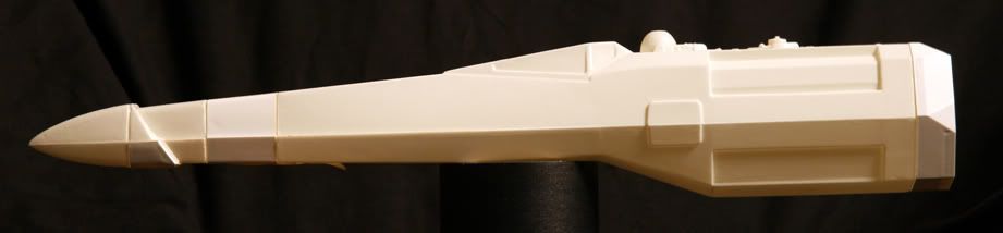
I processed the x-wing pictures with a program called PTLens. The software automatically corrected the distortion based on the camera model and focal length information contained in the EXIF data in the picture files. In some cases, the distortion was obviously not fully eliminated; you can see here, for example, that there's still some visible curvature on the upper wing, which was only about six inches from the camera:
but overall, the results seem fairly close to perfect.
Next, I loaded the pictures into Autodesk Imagemodeler, which I used to calculate the positions of virtual cameras in 3d space. At this point, a certain amount of human error is added to the residual distortion error because to create the cameras, you define points in each image which correspond to points in the other images. For
complete mathematical accuracy, you would need to determine the exact position of each point to the smallest fraction of a pixel. Imagemodeler determines the average position of the intersections between projected rays from each camera, and indicates the error for each point in each picture. Of the 212 x-wing pictures, I found that 45 had no errors greater than about 0.5mm, so I imported those virtual cameras into 3ds Max.
As a reference measurement, I chose the Airfix Saturn V part 44. I decided that, because the rear of the part was sanded off for the x-wing, and because it's possible that the part might splay inwards or outwards to a certain degree - either theirs during the course of converting it into an x-wing engine, or mine, simply from having other parts pressing on it while it was sitting in the box - the longest measurement that I could absolutely rely on was the distance between the two bands of stringers. In hindsight, I might have chosen the length of the "plank" that runs most of the length of the part, but either I was too stupid to think of it at the time, or I had a good reason not to that I've since forgotten.
Anyway, I built a 3d poly model of the Sat V part and carefully aligned it to match the camera views to check that I hadn't made some stupid mistake with my calculations:
In the above image, the blue line is my reference measurement, the red lines show the 3d poly Sat V, and the green line is exactly 1mm back from the front edge, just to try and indicate that everything lines up pretty good, and isn't off by anything like 1mm.
Now, from a measurement point of view, here's the biggest fly in the ointment, and the main point of this long post.
I don't know whether
my Sat V is the same size as
their Sat V.
I've worked as an injection moulding toolsetter, although we never produced model kits. The factors affecting the size of an injection moulded part are shot weight, injection speed, injection pressure, holding pressure and cooling time. Plus, of course, once out of the mould and fully cooled, the part will change size slightly according to temperature.
Where I worked, the tolerance on a part that size would generally be .2mm or (for most parts, much) less, but I have no idea what the situation was at Airfix in the 1970s. Personally, I think it's extremely unlikely that the tolerance would be as high as .5mm, but lets be pessimistic and say that it was. Let's continue being pessimistic and imagine that my Sat V is at one end of the tolerance, and ILM's is at the other end. So my Sat V is 1mm smaller or larger than theirs.
Let's be pessimistic again and say that the matching errors that I've spoken of above are all working together, so that even though my 3d Sat V
appears to line up pretty good with theirs, there's an invisible .5mm error there, too.
The overall length of the Sat V part is a little under 91mm. So, pessimistically, every 91mm that I measure might actually be as small as 89.5mm, or as large as 92.5mm.
515/91=5.66. 5.66 x 1.5mm = 8.5mm
So, ultimately, the length of the Red 3 fuselage is almost certainly between about 506mm (19 29/32") and 524mm (20 5/8").


 angry
angry