Build Log - Thermal Detonator Build (KR/OR)

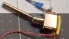
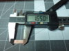
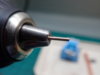
Next up is the aluminum part. I had to open up the insides to allow the red lens to move freely up and down but not too much that the lens will fall out or sit crooked. This took a lot of trial and error....sand, test fit, sand more, test fit...you know how that goes.

Edit: I also had to shave down (shorten) the base section so that there was enough spacing relative to the mid-section of the red lens for the lens to move up and down.
60201466_10214906231913836_5284530866259755008_o.jpg
 
Last edited:
Then the 3d printed part.... All the white sections are where I sanded and modded the hell out of this piece. Again lots of trial and error.
60147064_10214906226033689_1774811367245611008_o.jpg
 
Last piece is a shim to fill the gap between the lens/led and the aux button. So I raided my kids lego stash and found this button which is practically the correct diameter of the red lens and cut away the walls. Then cut a portion away to allow the wires to pass.
60149067_10214906231793833_6247631321942720512_o.jpg
 
All the pieces together and mocked up. Will try and finish assembly later tonight.

But before I forget, credit to Scarecrow for the ideas and photos of his build. Without his help, I would have been lost.
18.Red Aux 05 - Assemble 02.JPG

18.Red Aux 05 - Assemble 01a.JPG
 
Last edited:
A change of pace from wiring as I move onto the accent rods...

Some left over rods from a previous build....I think the copper would look good with the bronze steel chassis.
14.Accent Rods 01.JPG

Trimmed the rods to length using a jewelers saw.
14.Accent Rods 02.JPG

14.Accent Rods 03.JPG


Since I chose the steel chassis and we know that steel is not the best material for dimensional accuracy, the holes in the metal chassis had to be opened up. A quick run using a 1/16" drill bit helped but it wasn't enough.

Since the specs call for 1.5mm diameter rods and 1/16" is actually 1.59mm, you would think the drill bit would solve it right? Not quite...I had to reduce the diameter of the rods since I couldn't open up the chassis holes any more. So after throwing the rods onto my drill and a couple of rounds with 150grit sandpaper and 1000 grit finishing sandpaper all is good.
14.Accent Rods 04.JPG

Next, onto the final wiring....
 

Attachments

  • 14.Accent Rods 01.JPG
    14.Accent Rods 01.JPG
    2.4 MB · Views: 324
  • 14.Accent Rods 02.JPG
    14.Accent Rods 02.JPG
    2.3 MB · Views: 328
  • 14.Accent Rods 03.JPG
    14.Accent Rods 03.JPG
    2.4 MB · Views: 338
  • 14.Accent Rods 04.JPG
    14.Accent Rods 04.JPG
    2.3 MB · Views: 303
Wow - incredible work! I jumped on the latest run and mine arrived Monday. I'll have no problem weathering it, but this level of fabrication and electronics work is above my pay grade. Hopefully someone will come up with an electronics kit for it.
 
Wow - incredible work! I jumped on the latest run and mine arrived Monday. I'll have no problem weathering it, but this level of fabrication and electronics work is above my pay grade. Hopefully someone will come up with an electronics kit for it.

Thanks. The red aux was the biggest challenge. But I’ve seen other builds using an ardunio board that is more straight forward. But those were also with a 3D printed or resin thermal detonator and no chassis. The beauty of the chassis and electronics is that there is a home for everything. I know that Scarecrow is taking commissions if you want to go that route.
 
Hi,
Can you tell me how to connect the next room and tell me what it is called for my future research and the light used for the image in PJ?
More Thanks for return
Regards
 

Attachments

  • P2.JPG
    P2.JPG
    37.2 KB · Views: 341
  • P3.JPG
    P3.JPG
    41.6 KB · Views: 338
Hi,
Can you tell me how to connect the next room and tell me what it is called for my future research and the light used for the image in PJ?
More Thanks for return
Regards

Not sure I understand 100% what you’re asking but I’ll give it a go...

1) The photo with the long silver lever is the activation switch. Please refer to your board manual for wiring diagrams. But in general for the plector TD v3 board, you connect one wire to the activation pad and the other to + battery power.
2) The green light is a 3mm clear green led....meaning with no power, it looks clear. With power the led lights up green. You can buy these in different colors to suit your preference.

Hope this helps. Please ask if I didn’t understand correctly or if I wasn’t clear.
 

Your message may be considered spam for the following reasons:

If you wish to reply despite these issues, check the box below before replying.
Be aware that malicious compliance may result in more severe penalties.
Back
Top