T-47 Snowspeeder 1:1 full scale prop build

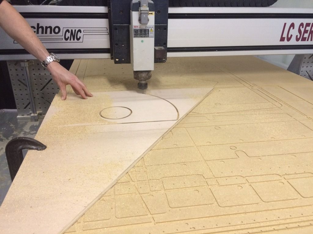
The cannons between the rear engine box and the front gun box changes dimension about 10 times over 3-1/2 feet. Each transition is a separately made combination of plywood frames and styrofoam bulk support rings. The fastest and most accurate way for us to cut these plywood frame is on the CNC router table. Hand routering or jig sawing them would work but would be much less precise. We tested the first piece on a left over piece of the 12mm plywood before committing a full sheet to the machine.


With a test front and rear frame, we glued and nailed three 9" long spacers in place. The rest of the open void will be filled in with foam to support the .090" thick fiberglass skin that will get wrapped around the frames.


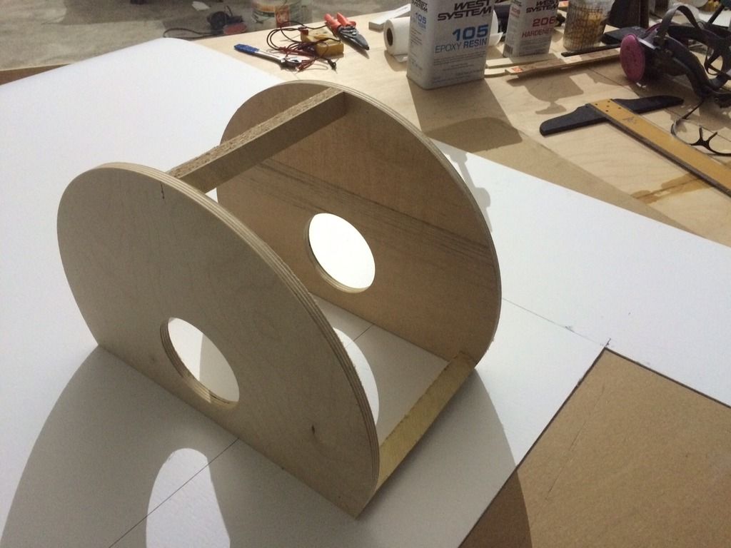
Once satisfied of the fit, we cut the next batch. Inside and concentric to the O.D., each frame has a 4.560" hole cut that is center-line positioned 3-1/2 inches off the flat bottom wing deck.


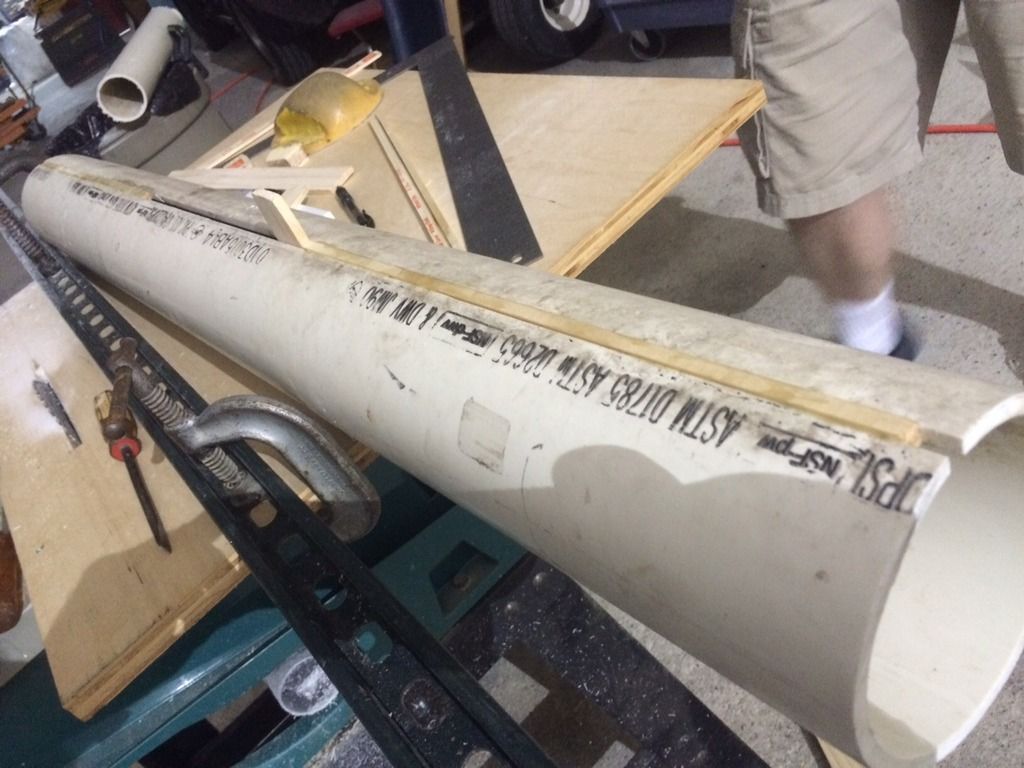
This center hole is what will perfectly align each section on a center support alignment tube that allows the 12 foot long aluminum gun barrel to slide inside and run to the rear anchor point. The support tube is a 4" I.D. schedule 80 PVC pipe. The problem is, a perfect 4" outside diameter (O.D.) aluminum tube can't fit inside of a perfect 4" inside diameter (I.D.) PVC tube. The tolerances are just too tight, and we need to be able to remove the aluminum gun barrel for transportation and repair work. The solution was to split the PVC tube down its length using the rotary saw. We pried open this cut line and glued in 1/4" wide wood shims. This opened the I.D. about .030" and made the two fits very snug, but removable. So far we have been using Gorilla clue for the foam and wood work. This is our first time using this water activated urethane glue and we are very impressed with its versatility.


The foaming bubbles that are at the edge of the wood and the fiberglass skin is the Gorilla glue after it has activated and expanded. It's great for filling loose fitting joints or gaps in the foam support frames. After it dries, it is easily sanded or razor blade scraped off. Less expensive than epoxy, and quicker to work with since there is no measuring and mixing of A & B parts.

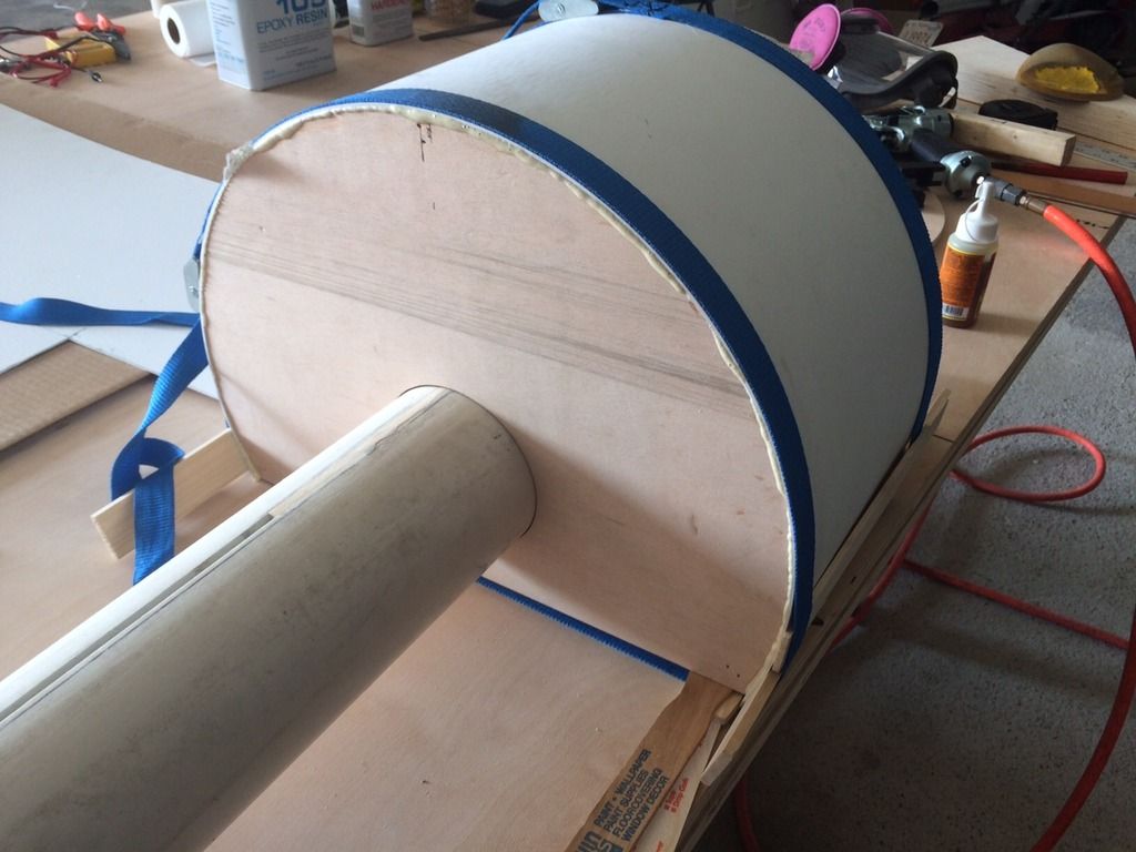
This is the largest drum diameter of the cannon body. 17.375" diameter by 10" long. The drum is glued into place on the PVC alignment tube. We'll start building the other diameters and assembling them the same manor. The blue tie down straps keep tension on the skin while the glue sets up over a 30 to 60 minute period.

 
Last edited:
Houston for ComicPalooza May 22 -25. You south Texas fans, let me know if we will see you there. It would be helpful to have a couple of pairs of extra hands on call for setting everything up.

Such an awesome build, can't wait to see it. I'm in north Houston, so I'll be at Comicpalooza with the Rebel Legion. Feel free to give me a shout if I can be of any assistance to you guys.
 
Wednesday April 22. 29 days to Houston ComicPalooza deadline.

Building more of the cannon sections. The next step down is a tapered 2-1/2" long section.


Same process for the flat sections of the 4 and 5-1/2 inch long sections. We only have two blue straps so the others are being held in place by pallet stretch wrap. It's been a useful tool for holding parts together while waiting for the resin or adhesive to kick.


Talking with the ComicPalooza owner again today about how they want to stage us. I sent him this quick drawing of how he might consider setting us up in the room.


I also sent him this picture as an example of what we are shooting for with the background Echo Base hangar scene. This picture is borrowed from a fantastic diorama scene that I found on images.


The plan is to have a 20 foot wide by 8 foot tall ice wall maintenance bay for the speeder to be parked in. Seeing as we don't have much time, it will probably be pretty simple for this show. But given time after May to work on it, we will add the light sconces and more hoses and eventually some fake fog, frozen ice effect oozing out of the bottom of the wall, to give the area a frozen cold feel.
 
Thursday April 23. 20th day of construction. But we didn't build anything....

Tonight we went to tour the Dallas Maker Space in Carrolton, TX. http://dallasmakerspace.org

They have assembled a fantastic selection of tools and equipment. We signed up for membership and are awaiting some of the next training classes to get certified for using the big equipment.
It is great concept and we met a lot of great and creative people there. I realized that you have to be patient and get to know how things, both machine and social, operate. In order to protect the collective investment in the expensive hardware, training and certification by committee has to passed before being allowed to work independently with the major, and dangerous, equipment. I really like the way they have it set up. But for this speeder project we are on such a self imposed tight time schedule that I doubt we will be able to use much of the facility for this build.

Well done DMS.
 
Last edited:
Friday, April 24, 2015.

It's time to get serious about the canopy. I've been practicing my Autocad skills and over the last few days drafted the canopy panels. I originally learned Autocad at A&M back in 1988, but have not done much with it in all these years. But it came back to me pretty fast once I dove into it again. First printed off a scale plotted paper model and cut and pasted it to confirm I had drawn it correctly and like the developed angles.

We would have preferred to have built this canopy in house. We are confident that we could have sawed and routered all of the cuts by hand to an acceptable accuracy and then ground and sanded all the edges smooth, but we wised up and realized time was not on our side. And even though we do have a 4 foot metal break, it would have really struggled to crisply bend this 1/10 inch thick 2024-O aluminum. The work around for this plan was going to be to router with a 90 degree chisel point tip, a pre-fold line into the underside of the panel, half way through the .100" thickness. That way we would only be bending .050" thick material and it would have been very crisp and accurate due to the fold line. The problem still was that some of the folds are longer than 4 feet and add to that the bending break's frame would get in the way of the folded side panels once we started bending this complicated beast. And admittedly, our aluminum welding skills are not very refined. Our welder is only a 60 amp unit, and we have been told that you really need at least a 100 amp unit to lay down a quality TIG bead weld on a panel this thick. So time and all these limitations conspired against us, so this will be the first time we have had to hire out a phase of one of our builds. May the RPF forgive us of our inadequacies.


After talking with a few water jet and welding shops around the area, we chose to work with Industrial Conveyor in Haslett. A really good group of guys interested in helping us with this funky project.

We sawed off a 9 foot section from one of the 15 foot long x 5 foot wide panels. Loaded on the trailer and delivered it for cutting, bending and welding at their shop on Hicks Airfield. We like working with other airplane guys.


Their water jet table. In operation it kicks up quite a mess.


The canopy after being water jet cut. Accuracy on the cuts is +/- .002" Very impressive.


Each fold in the metal is set up by hand on the ram V press. There is more art than science in making great things come to life. These guys are experienced and creative when it comes to working strange shapes.


The canopy after being bent into shape. Each edge has a 1/2" flange bent inward to stiffen the panels.


The back stationary half of the canopy system that will hold the hinges and lifting cylinders is being welded.


The canopy is welded to close the side and front panels.


A view form what it will look like from the pilot's seat. This is what I have been seeing in my minds eye all this time as I envision the completed speeder.


Looking down through the "sunroof" panel above the pilot's head.

 
Last edited:
Saturday April 25. Day 22:

Back to focusing on the front grill work on the engine pods.


Checking alignment along the gun barrel center line.


About half of the cannon cylinder pieces finished.


Cutting and applying the grills on 1" centers. 3/4" wide by 1-1/2" expanded styrene plastic grill bars. Great stuff, stable and solid to machine.


Gorilla Glue and 2" air nails. Speedy and precise.

 
Last edited:
Sunday April 26, 2015.

We've set the final position of the engine and gun pod boxes in relation to the center line of the cannon sub-assembly. Now trimming the edges of the boxes to have a proper 1" side height edge on the gun and a 2" side wall edge on the much larger engine box.


I found out how to do a screen grab from a DVD on my computer. The secret is, "ask a 14 year old." They know everything. We watched all of the Hoth interior scenes to get a better feel for how the ice craved walls looked. We determined everything seems to be made in 4 foot wide panels of random waviness foam panels panted glossy white with a few fake ice cycles added in places. That was exactly how I envisioned building my back drop hanger maintenance bay walls. It's nice to know mine will be produced the same as the original stage ones were.


We've ordered eight 4'x8' x 3inches thick slabs of 2 pound styrofoam from the guys that supply our regular packaging foam. We will cut the wavy lines in it with a 4' wide hot wire bowsaw.
 
Monday April 27. 24 days till the Houston Comicpalooza, load it on the trailer and drive 5 hours south, deadline.

Now that we have two vehicles to display, we needed a much bigger trailer. My previous 16' open flat bed trailer served valiantly, but offered no protection form the rain and road grime. And to be honest, driving down the highway with a Landspeeder fully exposed on an open trailer is a TRAFFIC HAZARD !!!. Drivers go crazy and loose all sense of safety and self control taking pictures. Speeding up and slowing down and changing lanes to get different angles. So with all this as lessons learned, I bought a 25' long fully enclosed car hauler. Everything but my gas mileage efficiency will be much better now. Good thing I have a Hemi.


Really liking the solid ramp on this style of trailer. It's a bit old and experienced, but we'll love it like it's a shiny new penny.

 
Last edited:
Yeah, this is rapidly edging into "one of the best threads ever" territory. Jeez louise, that canopy.

Thank you Cayman Shen. That's very motivating to hear. I'm mostly entering these post at about 2am after a full day's work and then 4 to 6 hours each night working on the speeder. I worry sometimes if my writing is even comprehensible.
 
Tuesday April 28. Day 25.

Welding aluminum is an art that we haven't mastered yet. Mostly we need a proper TIG welding unit and a higher amperage feed to the circuit box. The artist that did the welding laid down a beautiful 100% coverage bead along the two front panes of the canopy and the rear canopy mount housing.


As much as I admire the rugged, industrial raw look of that weld, the speeder canopy is supposed to have smooth rounder 1/8" radius edges. So out comes the air powered sanding wheels and away we go. Keeping light hand pressure and working an edge on the sander 80 grit and 120 grit pads, removes the high spots of the weld while feathering in the edge of the panel to a sharp angle. After the edge is established, repeated long stroke passes down the length of the edge sculpts a 1/8" radius into the corner that will match the bent folds in the other panels. Making the finished product look uniformly bent and making an observer wondering how it was made. When its done right, all evidence of a welded seam disappears. Ready for some light epoxy primer filler, sanding and paint.


The canopy sitting on the freshly cut cockpit 3/4" floor panel. Everything is lining up precisely.


Last edited:
Wednesday, April 29.

I'm backdating these posts to accurately record each days work progress. It's been almost a month since my last update. After 3 conventions in a row at the end of May, I needed to take a break from working, non-stop on the speeder, and catch up with "real life" stuff. Now I'm back at it and will try to catch up on chronicling the build report.

Once we had the canopy completed, it was time to begin the cockpit body and sub-structure frame of the undercarriage. Autocad has been a useful tool for solidifying design ideas that until now, have just been floating in my head. These are the bulkhead sections for the main body tub.

Bug help from you Autocad 2015 experts. At certain zoom levels, my dimensions text have all these random spider web artifacts. As I zoom in and out the disappear and shift about. No biggie, just frustrating.


The front bulkhead. 3/4" plywood.


Temporary 90 degree support braces tacked in place with the nail gun while the urethane glue dried.


Side walls . All 3/4" plywood.


Rear bulkhead. The stubby wings will be the upper supports for the speeders wing panels.


With the canopy in place just to see how it's gonna look when complete.

 
Last edited:
Back
Top