SW – ANH (5 Foot) - Studio Scale Millennium Falcon Build

Hello everyone,

Thank you for your valuable aids your information and your quick response , it is really nice to you!

Stu , I answered you :)

I am far from the truth about my measurements !!

A later for new adventures in a distant , very distant galaxy !!!;)
 
Last edited by a moderator:
Ah man...I was hoping the measures for the engine vents requested by blackeagles was going to be posted here too....guess I could request eagle1 to send me the info too? yes-no eagle1?

Also was wondering about the depth of the floor in the maintenance pits on the mandibles?

One other thing I have always wondered about is how are the mandibles attached to the main saucer body? What keeps them secure? Do they insert into it a bit, or just hang on there?

imurme

PM sent
 
Andre, I hate to bother you again ;) Hopefully this will be the last time for a while. I was drawing up a full scale drawing with your dimensions. I had a couple of dims' that weren't on the original top view. One is the distance from the X axis center line to the cutout on the front saucer. And the diameter of the Radar Dish well. I opened your top print in Photoshop and got the following dimensions. 15.665 " for the cutout dim, and 4.25 " diameter on the dish well. I will post the drawing with the dims in red. Sorry to keep bothering you, just wanted to double check my measurements. The ole eyes aren't as good as they used to be, LOL. Thanks

Joe

Top Dims Cropped.jpg
 
Last edited:
Andre, I hate to bother you again ;) Hopefully this will be the last time for a while. I was drawing up a full scale drawing with your dimensions. I had a couple of dims' that weren't on the original top view. One is the distance from the X axis center line to the cutout on the front saucer. And the diameter of the Radar Dish well. I opened your top print in Photoshop and got the following dimensions. 15.665 " for the cutout dim, and 4.25 " diameter on the dish well. I will post the drawing with the dims in red. Sorry to keep bothering you, just wanted to double check my measurements. The ole eyes aren't as good as they used to be, LOL. Thanks

Joe

View attachment 451447

I'll jump in here just 'cause I think this is an area I got wrong in the cad.

We originally had the short sides of the front cutaway as being radial; pointing toward the center of the dome. But it became clear that this would've been too severe a solution.

So the next iteration had them parallel to the front plane. This was definitely closer. But I think we need another rev.

I now think those short edges are perpendicular to the mandible side wall. But I need to model that to verify. Basically, measure to the back edge of the Wankel, and cut 90 degrees from there.

The cross-over point is pretty close in the drawings, but the angle isn't right.

---------------

Ignore this ramble... When I put my tin foil hat on, I actually think it's a bit less than 90, as these were cut at a time during the model build when the mandible interior walls were parallel, during a dry fit perhaps. Then an edit was made to toe-in the mandible sections and here we are; the cut was made and not changed. There are some other things I've observed that point to this being the case... These other things of course escape me at the moment. But there were definitely times while modeling that I thought, X would make more sense if these were rotated outward...
 
Thanks Man, sorry I don't know you're given name, ;) Don't know why I'm sweating this area as it will be under the plating. Guess since I'm making a mold I want to be close. I'm not to that point yet. I was just making a full size drawing and wanted to double check. I will be using inserts in my mold to make the front and back hull sections, so I can change this section at anytime. Thanks for your reply and all your work, Cheers,

Joe


No worries. We're all in this together.

If you look at Andre's post here, there are some good comparison shots of our digital survey and the actual 5' model regarding this area. It illustrates what I'm talking about pretty well. The Wankel nest up against that edge - and while it is covered in armor, you'll see into the sidewall wells from the other side, so it'd be good to get that cut right.


Cheers,
Joshua (by the way)

: )
 
Thanks Joshua, I'm pretty perfectionist about these things. I hear they make a pill for it, but it's out of my budget, LOL. I appreciate the good work you guys are doing, and want my model to reflect that. I wouldn't even attempt this one, if not for all the info being made available. Thanks again,

Joe

P.S. Was I right about the 4.25 " for the radar dish well ?
 
I'll jump in here just 'cause I think this is an area I got wrong in the cad.

We originally had the short sides of the front cutaway as being radial; pointing toward the center of the dome. But it became clear that this would've been too severe a solution.

So the next iteration had them parallel to the front plane. This was definitely closer. But I think we need another rev.

I now think those short edges are perpendicular to the mandible side wall. But I need to model that to verify. Basically, measure to the back edge of the Wankel, and cut 90 degrees from there.

The cross-over point is pretty close in the drawings, but the angle isn't right.

---------------

Ignore this ramble... When I put my tin foil hat on, I actually think it's a bit less than 90, as these were cut at a time during the model build when the mandible interior walls were parallel, during a dry fit perhaps. Then an edit was made to toe-in the mandible sections and here we are; the cut was made and not changed. There are some other things I've observed that point to this being the case... These other things of course escape me at the moment. But there were definitely times while modeling that I thought, X would make more sense if these were rotated outward...


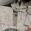
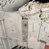
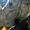
Ok, maruska...I'm glad this has been brought up, I have always wondered about this area...I also haven't agreed with the choice to flatten out the angle of the cut-in on the overhang at the front mandibles...in fact I still may believe it to be rather severe, perhaps back in line with the center of the dome...but it is such an elusive area to pin down, especially on the port side...but what I think might help is looking at the opposite side, under the cockpit...it seems more clear and perhaps shows what is happening better...so if you can try and explain to me what exactly is happening in these shots it may help clear this up some for me???

Bottom-Front--4_crop.jpgBottom-Front--7_crop.jpg111_SWI_0114_crop.jpg

It seems to me (and I may be getting cross-eyed here) that the angle starts out pretty severe, then as it reaches the end of the overhang it flattens out with the plating to be in line with Wankle engine part? Am I seeing this wrong? The angle does seem to follow along with that gray colored plating as it goes inward, which points to near the center too?

Truly Confused,
imurme
 
Hi all,

Bwayne64,
I think it is a "bay technical maintenance " circle 4.25"
Bonanza parts 01.jpg
In terms of the radar dish I that :
- The first image is from the site, but I do not know where
MF_dockingRingWIP_002.jpg

the second is a photo found in a book I have ,
20140731_183625.jpg
it may be able to help you :)

Bonanza parts 01.jpg


MF_dockingRingWIP_002.jpg


20140731_183625.jpg
 
Last edited by a moderator:
Hi all,

Bwayne64,
I think it is a "bay technical maintenance " circle 4.25"
View attachment 451661
In terms of the radar dish I that :
- The first image is from the site, but I do not know where
View attachment 451662

the second is a photo found in a book I have ,
View attachment 451663
it may be able to help you :)
The central cone in the radar dish is from the Airfix /144 Saturn V. It's the second stage bottom, I think. That's the part I'll be making as my first contribution, since I have the kit.
 
Last edited by a moderator:
Joe,

As for the diameter of the radar dish well, I'm guessing 4.25 inches.

It's hard, with the reference I have, to peek under the plating in that area so I basically went with what it could be and what might look nice - some gap but not too much gap!

Screen Shot 2015-03-16 at 12.04.05 PM.png


apb

Andre, I hate to bother you again ;) Hopefully this will be the last time for a while. I was drawing up a full scale drawing with your dimensions. I had a couple of dims' that weren't on the original top view. One is the distance from the X axis center line to the cutout on the front saucer. And the diameter of the Radar Dish well. I opened your top print in Photoshop and got the following dimensions. 15.665 " for the cutout dim, and 4.25 " diameter on the dish well. I will post the drawing with the dims in red. Sorry to keep bothering you, just wanted to double check my measurements. The ole eyes aren't as good as they used to be, LOL. Thanks

Joe

View attachment 451447
 
Joe,

As for the diameter of the radar dish well, I'm guessing 4.25 inches.

It's hard, with the reference I have, to peek under the plating in that area so I basically went with what it could be and what might look nice - some gap but not too much gap!

View attachment 451816


apb


Thanks again Andre, That sounds good to me, and even if it were off a few microns, who's gonna know, :) Hopefully I won't have to bother you guys again for a while, ;) Don't want to wear out my welcome. Cheers,

Joe
 
Hey Andre,

Do we have plans for a version 1.1 release of the blueprints and CAD files? I know the forward cutaway was on my list. Have you been tracking any other changes?

J.
 
Hi all,

Bwayne64,
I think it is a "bay technical maintenance " circle 4.25"
View attachment 451661
In terms of the radar dish I that :
- The first image is from the site, but I do not know where
View attachment 451662

the second is a photo found in a book I have ,
View attachment 451663
it may be able to help you :)

Thanks Man, I believe that last pic is of the mysterious large scale dish. It's a print I've never seen before. That's a good find. Appreciate the assist. Cheers,

Joe
 
Last edited by a moderator:
The central cone in the radar dish is from the Airfix /144 Saturn V. It's the second stage bottom, I think. That's the part I'll be making as my first contribution, since I have the kit.

Yep, I have that kit also, it's a crossover with, well, everything, LOL. I got mine for the Galactica. I think somebody said earlier that the dish itself was around a 6 inch plastruct part. I think a tank cap. Let us know if you confirm this. If this is true it won't be in scale with the large scale dish they built. The print above shows a 4 foot base and a 8 foot dish diameter. Of course why would they make it easy for us, :) It should be easy to scale the 5 footers dish with all those parts on it. Unfortunately I thought the ammo can looking things were from the 8 rad, but they were from some other kit. Sealab 3 I believe. A kit I've yet to acquire. Gotta get one of those suckers when I when the lottery, ;) Cheers,

Joe


Here's the Plastruct Elliptical domes Page, the 6 inch dome looks a little deep, but that's the one I read was the main dish part.

Plastruct Domes.jpg
 
Last edited:
Joe,

The elliptical domes are too deep, I'm afraid. I modeled and did some 3D track matching to the clear acrylic dished domes dimensions:

[video=vimeo;87213359]https://vimeo.com/87213359[/video]

1BUWEaIAEQAIqBVBGp J6RVFVAYRAAiABGACEAEIAItCAHY9regyoCmQAQgAhABiABEQA  cIwLZfByBDFRABiABEACIAEWhBCMC2vwVVBjQFIgARgAhABCAC  OkAAtv06ABmqgAhABCACEAGIQAtC4H8 j NlKqAHjAAAAABJRU5ErkJggg==


I believe VHD-600 is the one we want for the "5 footer"...


Screen Shot 2015-03-16 at 6.07.07 PM.pngScreen Shot 2015-03-16 at 6.07.24 PM.png


Regards,

Andre

- - - Updated - - -

Joe,

The elliptical domes are too deep, I'm afraid. I modeled and did some 3D track matching to the clear acrylic dished domes dimensions:

[video=vimeo;87213359]https://vimeo.com/87213359[/video]


View attachment 452057

I believe VHD-600 is the one we want for the "5 footer"...


Screen Shot 2015-03-16 at 6.07.07 PM.pngScreen Shot 2015-03-16 at 6.07.24 PM.png


Regards,

Andre
 
No current changes from me.

We could update when your cutaway is ready to integrate...


apb


Hey Andre,

Do we have plans for a version 1.1 release of the blueprints and CAD files? I know the forward cutaway was on my list. Have you been tracking any other changes?

J.
 
This thread is more than 3 years old.

Your message may be considered spam for the following reasons:

  1. This thread hasn't been active in some time. A new post in this thread might not contribute constructively to this discussion after so long.
If you wish to reply despite these issues, check the box below before replying.
Be aware that malicious compliance may result in more severe penalties.
Back
Top