Studio Scale TOS Enterprise(11.25 feet)

Now THIS is the Enterprise (painted correctly)
bluescreen12-1.jpg

Here is a nicer pic of Datin and crew
datinandcrew.jpg

She was in rough shape before she got to the Smithsonian the first time
shewasinroughshape.jpg


Sir, your work is remarkable and I appreciate your generosity in sharing the process with us. I noticed that in Star Trek the Experience and Star Trek the Exhibition they NEVER seem to have the original Connie on display which is ridiculous since she was the first. I am hoping that if you intend to mold copies of this great model, that you intend to sell one to them to the aforementioned companies.

Keep up the fantastic work!
:)Spockboy

PS-This is my nod to TOS
YouTube - STAR TREK TORCH
 
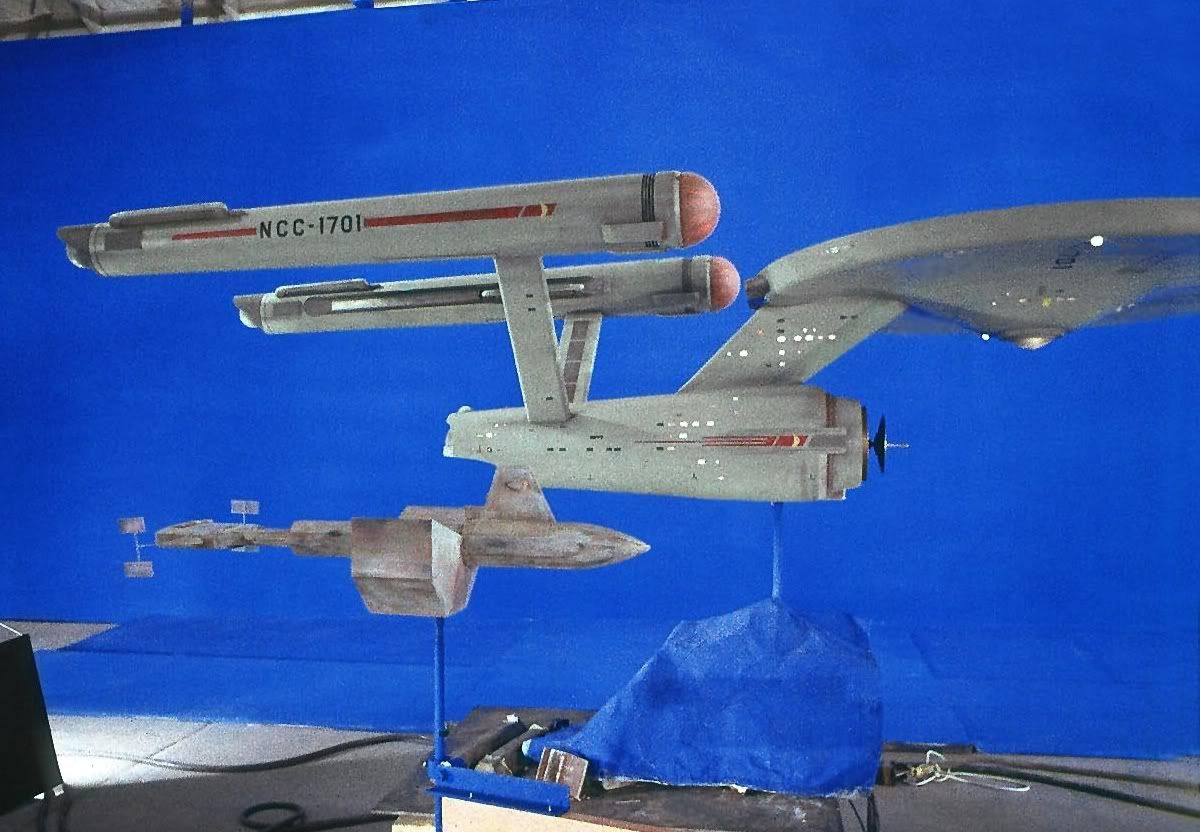
Funny how there isn't any sign of panel lines on the nacelles, 2nd hull, lower saucer. Thanks Spockboy, I always thought the same thing. The ST exibition that came to Phoenix was very very(I asked for my money back) disappointing.

I see this is your first post Spockboy, welcome to the RPF.

Now another update.
dscn2052f.jpg

You guys remember me showing you this.

If you remember those slots in the middle.
dscn2123g.jpg

I routed those out today, and put the nacelle together.

Here is how I did it-
dscn2125.jpg

I cut a 1" steel bar to fit each of the slots(they are 12" long). I use steel because of its strength, and hopefully it will not flex(it won't at that length, and the application isn't strong enough to be any problem).

But I do need to drill holes for screws.
So I use my trusty milling machine.
dscn2145b.jpg

Pardon the mess, this is a manual milling machine. To some it will look like a drill press on steroids. It does do a whole lot more than drilling holes. It weighs over 2000 pounds, and is precise enough to put my initials on Lincoln's eyeball(on a penny, I'll never do it. I can't see that well:lol).
It's main job is to use a cutter to shape any material(looks like a drill bit, but it can cut on the side of the bit. They are called endmills, and they come in a variety of shapes and sizes. I use them in router as well. I'll show more about that as the project progresses). It is an indispensable tool in any machine shop.

For this post I will be using it to drill some holes.
dscn2131k.jpg

Now in this pic you see a vise(blue thing to the left), a drill chuck w/drill bit(top). Below the drill bit there is a steel bar with holes in it. Now I needed to drill six holes in four bars. Some will think that could take all day. Nope it's whole lot easier than you think. The first thing I do is mark where I want the holes, I'm not showing that because the holes only need to be close to where I want them. Once I figure where I want them. I put the bar in the vise(tighten down).

Before I drill the hole I do something else.
dscn2129c.jpg

See that little red box with the shaft on the left side of the vise. It has many uses(I use it hold measuring devices, at times), it has a magnetic base so it can be moved around. In this application I'm using it for a stop. It's placed at the end of the bar so I can drill holes in the same place on each bar. And since I need holes the same distance from each end of the bar, I just flip the bar over and both sides are taken care of. It really is that easy, and you can do the same trick with a drill press.

dscn2133y.jpg

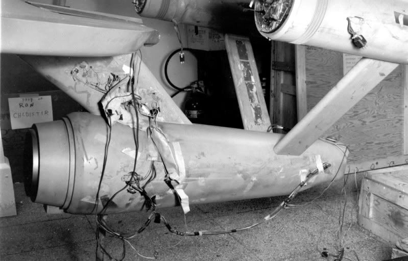
Next I place the bars in the slots. The fit is excellent.

dscn2138h.jpg

Here is one side of the nacelle with the template removed, and the bars screwed into place. The nacelle is now one piece.
Next-
dscn2139y.jpg

I place a pin at each end. So I can put the nacelle together for sanding/matching.
dscn2142w.jpg

I placed an end cap on each end of the nacelle. So I can keep things together. It's notched so the cap is centered.

dscn2144w.jpg

Here is the Nacelle in one piece. I have started to sand and it will take some work to get everything right. It's fit is much better than some mainstream kits I have. :lol

That's it for now, any questions comments?
 
I realize you're making this to be molded but I gotta know. How much are these peices weighing in at so far? I'm sure they aren't light!
 
Looks great! The fits are excellent.

And yes no panel lines. Not even the dark gray under the nacelles where they meet the pylons. ;)

Steve
 
The pieces aren't light, but they aren't as bad as you might think.
I'm more concerned about stability than weight.

As far as I know it is the largest fan built ss model. Some other guy apperntly made an 11' TOS E(as a one off), but unless he does more than post a single youtube video. I think I might be taking the title.
The only other one I know of is the ss 8' Star Destroyer, that I consider a much greater effort(that ship is greeble heaven or hell).

There are times I think the SS Discovery would be an interesting build:lol. But it wouldn't be very practical to build or display. Much less transport(even broken down).
 
The Discovery, 54 feet long, with the smaller model being 15 feet long. Words could not describe the modeler who tries the big one.
 
Here is another satisfying afternoon in the shop.
dscn2158c.jpg

Again pardon the mess, that's what happens in my shop. Especially when using hand tools. Most of you know the 2nd hull of the E, I put it together with the same technique as the nacelle.
dscn2154hw.jpg

With one exception, no pins, I had to do the old fashioned way. The parts were off when I machined them, so I couldn't use the pin trick. That's more of a convenience, the parts were fine except for that one flaw. So I use the templete to align the 2nd hull to the neck. If you look just to the right of the bars you'll see some chrome disks. Those are washers I place those in key spots so I can match each side of the 2nd hull. I placed those along the spine and the front of the hull. Then route out the groves for the bars.
dscn2156yl.jpg

Here is without the template, there is a gap between the parts. I'll fill it in with bondo later, the only thing I had to be careful of was using screws that were to long. The neck isn't all that deep, I did break through a few times. That's not a big deal at this stage. Nothing filling and sanding won't take care of.

dscn2169l.jpg

I figured you guys would want to see these parts together. If you look in the middle of the image there is a 1-2-3 block there for scale.

Now onto something else you guys might find interesting.
dscn1619vf.jpg

Here is the upper saucer, I ran this part back in October.

I wasn't entirely satisfied with it(you guys know how that gets). So instead of spending endless hours trying to get it right. I'll run(machine) the part again. So I have my router place the part's locator pins(that's drilling holes). I do that so I know where my origin is(0,0,0 that's so the router can machine over the original part without cutting into the original surface), and place the part in the machine.

First step-
dscn2146k.jpg

Re-coat the part with a thin layer of bondo.

Next-
dscn2148s.jpg

Machine the part, I did what is called a rough cut(at .03" spacing, it took the machine about 12 hours). It's the first pass to see how well I coated the part, and to catch any voids and major pin holes. The red marks in the part are voids.

Next-
dscn2153r.jpg

I fill in the voids and large pin holes with bondo. This time I'm trying something different. Since the part has an endless number of pinholes, I figured I would try glazing the part before the final pass. Just to see what would happen.

Well...
dscn2161h.jpg

I started running the part this morning, this is what it looked like in the afternoon. All of the red dots are pin holes. Here is is a little closer.
dscn2162e.jpg

Kind of interesting to see just how many pin holes there are.

My machine is running right now, and it will run well into tomorrow. The final pass I'm running is going to take well over 33 hours to complete. Why? You ask, well I'm running a very fine spacing .01". That's one hundred passes for every inch of the upper saucer. The reason I'm doing it so fine is so there is less work later. It means less sanding and (hopefully) less filling in pinholes.

To be continued...
 
I just about fell outta my chair, then sat transfixed reading this whole thread. Awesome work and the explanations and pictures of the process are fascinating. Thanks for taking the time to post!!!!!
 
This is a fantastic project :thumbsup

for a great bondo tip, don't mix in a bowl and stir until the components are mixed, this adds a lot of air and lots of pinholes.
spread the bondo on a flat surface and use a spatula kind of tool, just press the components together, this will greatly reduce pinholes.

What Xeno said!
 
This is an amazing project - and an amazing workshop as well !
What I really like about what you are doing is educating all of us in the process. Most will never have the opportunity to tackle such a grand project, but it can be an informative journey nonetheless.

With technology moving forward, we might see some of what you are using in a home shop environment yet.
 
With technology moving forward, we might see some of what you are using in a home shop environment yet.
Funny, my shop is in my garage.
The hobbyist CNC market is very well established, and it's amazing what some of those guys do. It takes a little knowledge, a lot of work, and a great deal of desire.
But if your looking for the easy way to do this stuff. This isn't it.

Continuation...

I was last machining the upper saucer, things were going well until...
dscn2174u.jpg

About midway through the job the router drops. Why I have no clue, but it's cutting below the surface I want.
dscn2171h.jpg

This happens every now and then(most of the time it goes up), the router will do something like this, then go back to cutting on the original plane. Most likely it's a software glitch, after all the code to run such a part has hundreds of thousands lines of code. There is bound to be some problems every now and then. Now I don't consider this a big deal, but it does mean creating a new tool path(this tells the machine where to cut) and reapplying bondo.
dscn2177.jpg

When I make a new toolpath, I change it's spacing. In this case I tell the machine to cut at .02" spacing, that's 50 passes per inch. It took less time(about 17 hours).
dscn2191a.jpg

Things went fine this time. I'm happy with the results. Then comes finishing the part for casting.
I'm sure some of you are asking why I do things this way. The main reason things like this are done is to make the next step easier. The part will take a lot less effort to get smooth than if I made the part by hand.
 
I'm sure some of you are asking why I do things this way. The main reason things like this are done is to make the next step easier. The part will take a lot less effort to get smooth than if I made the part by hand.[/QUOTE]

I think it's a brilliant way to to it. Not only will it be easier for you in the end but you will ensure symmetry when you join the pieces.

Awesome work!

:) spockboy
 
I was wondering when someone with the skill would tackle this model at this scale. Cannot wait to see the final result. One of the finished models should go on tour with the traveling ST exhibit, if indeed it is still traveling. One should be in the SF museum in Seattle, regardless of it being a replica.
 
Back
Top