xl97
Master Member
here ya go:
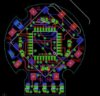
quick peek at the bottom.. and the pads marked that we'll use:
(bottom)
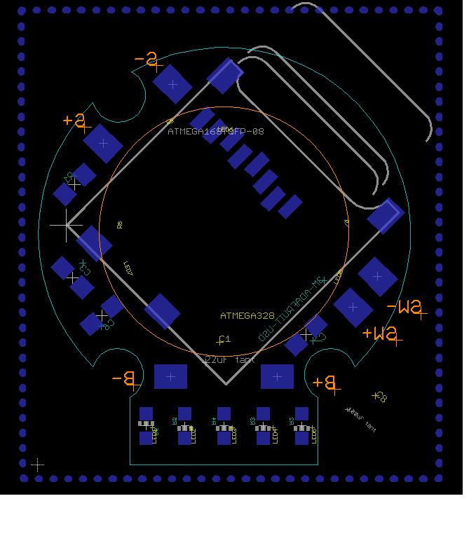
(top)
showing the leds and the main chip..
you can also see the 3 red leds I'll be putting on the top of the pcb AROUND the main chip.. the small component right next to each led is its resistor..
(big pads around the outside 'ring' of the top of the pcb are just pads I'll be using to program the pcb.. and will/should not be visible once assembled.. (they'll be hidden under the main bezel)")
one thing to note is that, since I went back and trimmed out a few more caps to make space..
I can put back in the 4th post into the pcb.. I was originally going to cut one post/leg flush on the 3D bezel piece.. (3 still would have made it stable and the pcb fit/lock int too, but its irrelevant now)
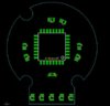
quick peek at the bottom.. and the pads marked that we'll use:
(bottom)
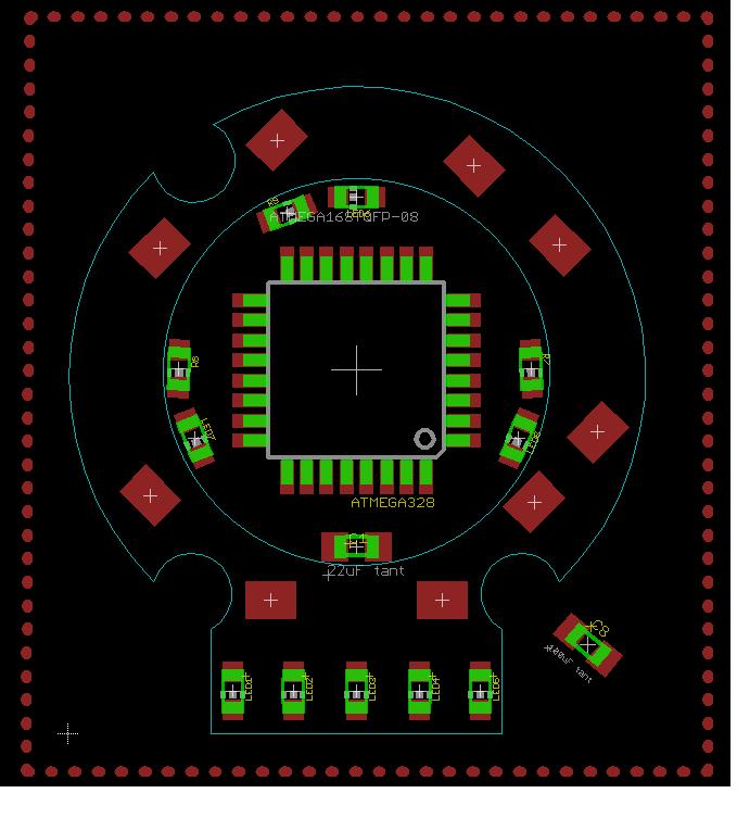
(top)
showing the leds and the main chip..
you can also see the 3 red leds I'll be putting on the top of the pcb AROUND the main chip.. the small component right next to each led is its resistor..
(big pads around the outside 'ring' of the top of the pcb are just pads I'll be using to program the pcb.. and will/should not be visible once assembled.. (they'll be hidden under the main bezel)
one thing to note is that, since I went back and trimmed out a few more caps to make space..
I can put back in the 4th post into the pcb.. I was originally going to cut one post/leg flush on the 3D bezel piece.. (3 still would have made it stable and the pcb fit/lock int too, but its irrelevant now)
Last edited: