Snowspeeder Scratch-build

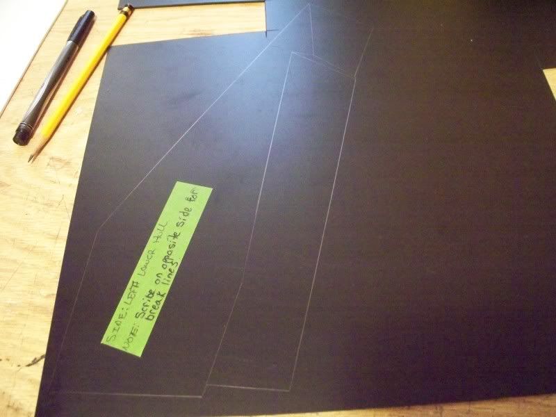
Well onto the lower hull.............
Ah ya the lower hull is one of those
things i go into expecting to get wrong......
at least a few times! But using some damage control
and taking notes helps, so does making the corrections
with cheap media.......like paper(if your a tree you
are probably not laughing right now.....sorry:angel)

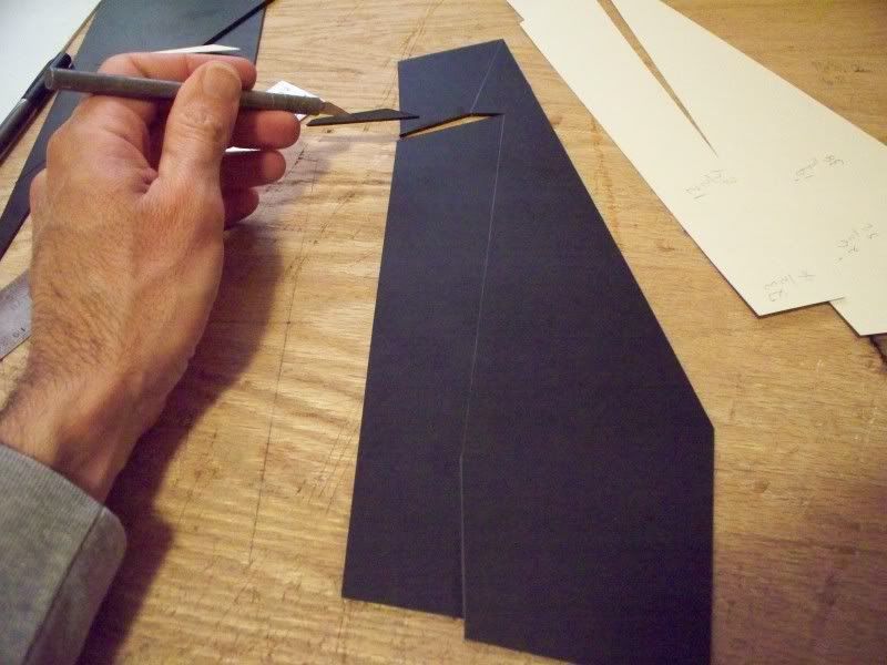
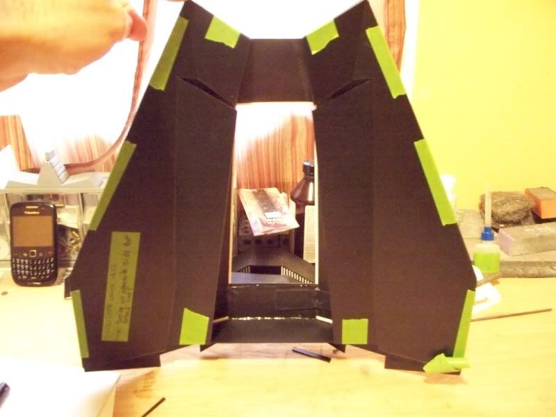
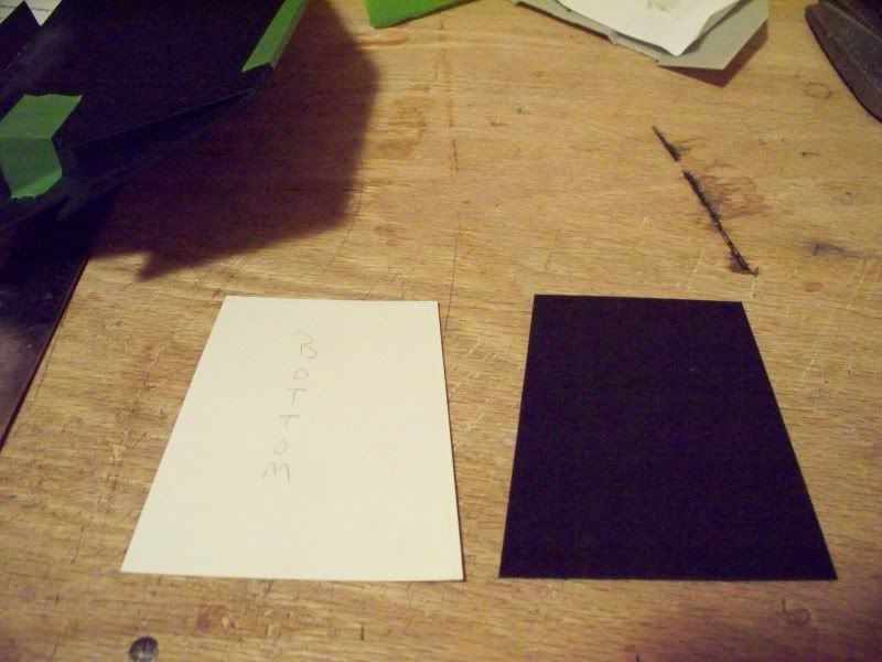
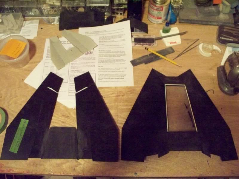
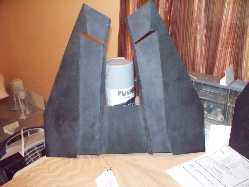
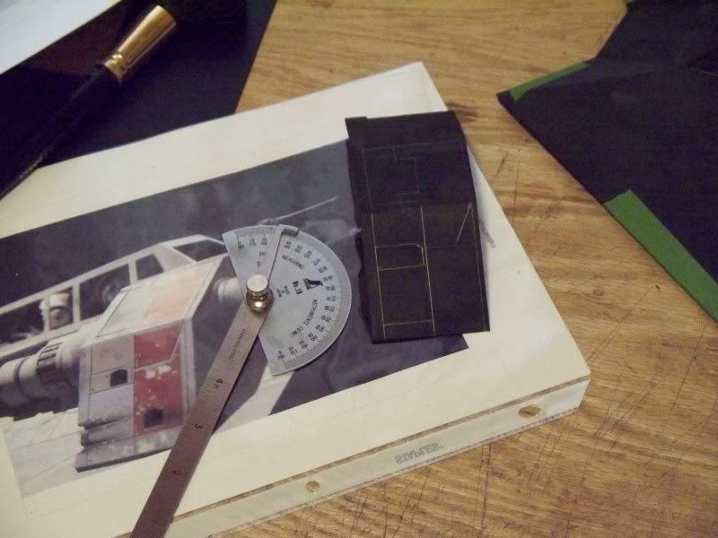
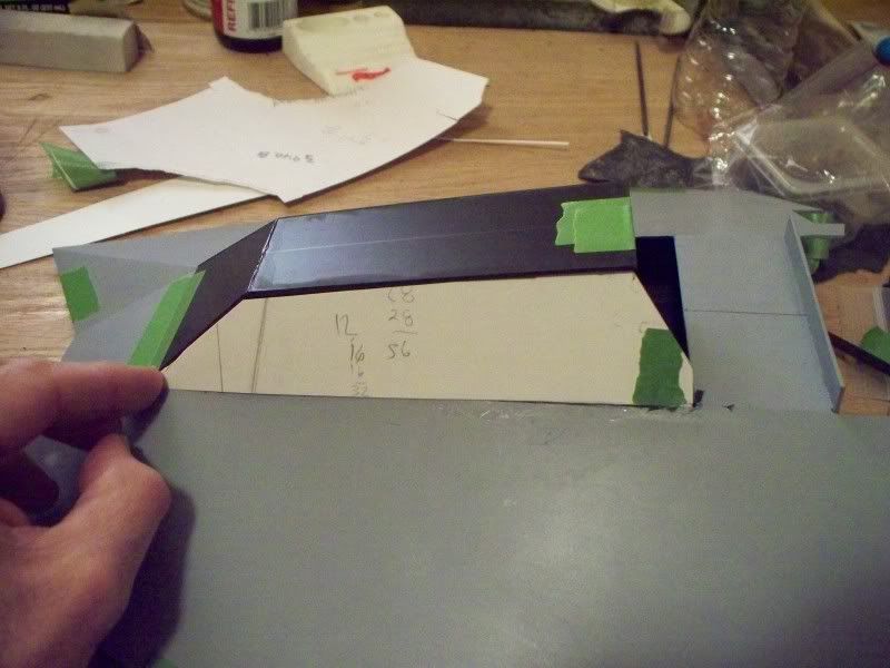
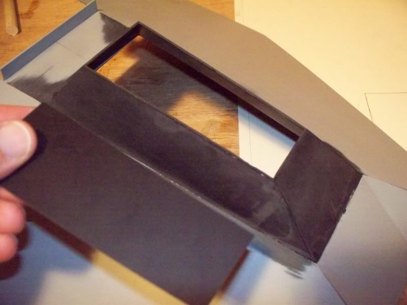
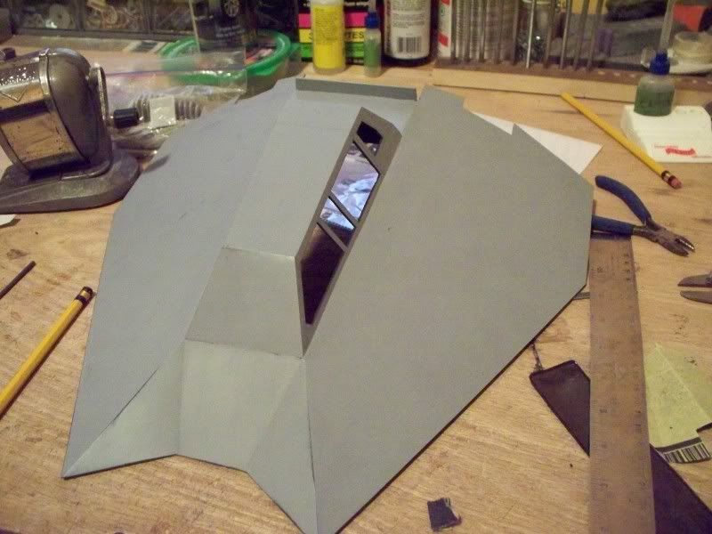
Any way first pic is not the lower hull but the
last pic of the canopy build.
100_3189.jpg


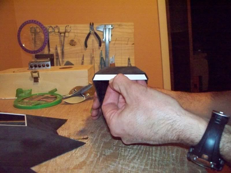
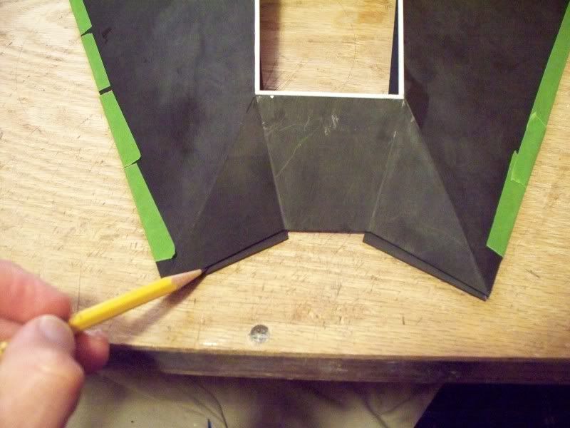
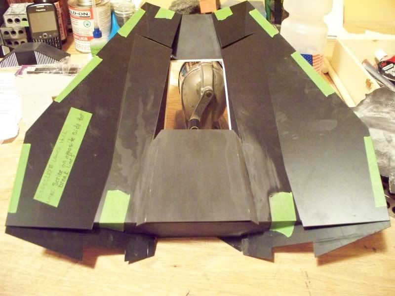
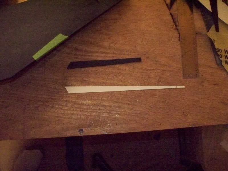
if you dont have one of these tools get one,
and use it to cheat as much as you can, as
you see me doing here to help figure out the
angles on the lower hull. Ah ya Micro Mark
has them if your considering.:thumbsup
100_3190.jpg


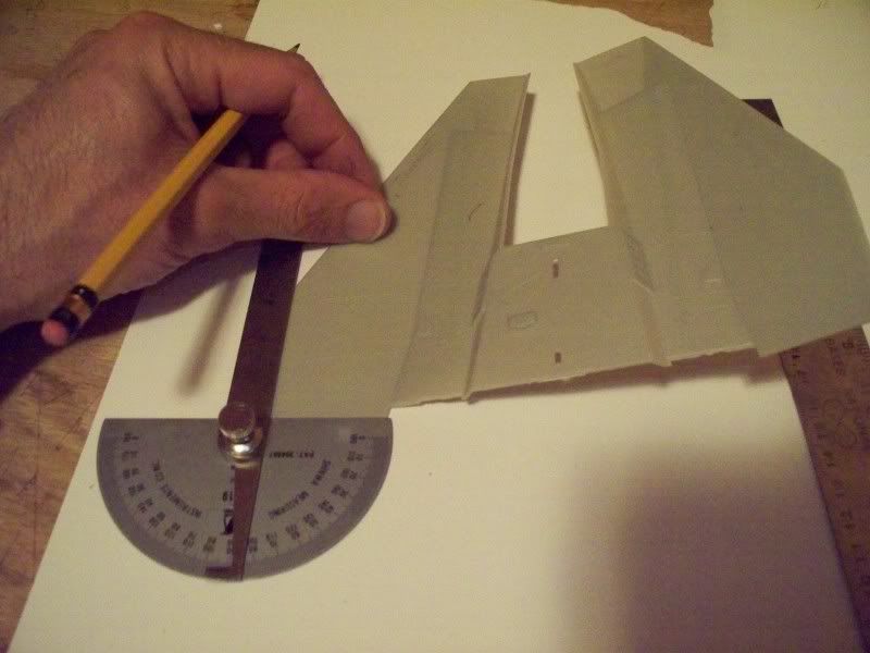
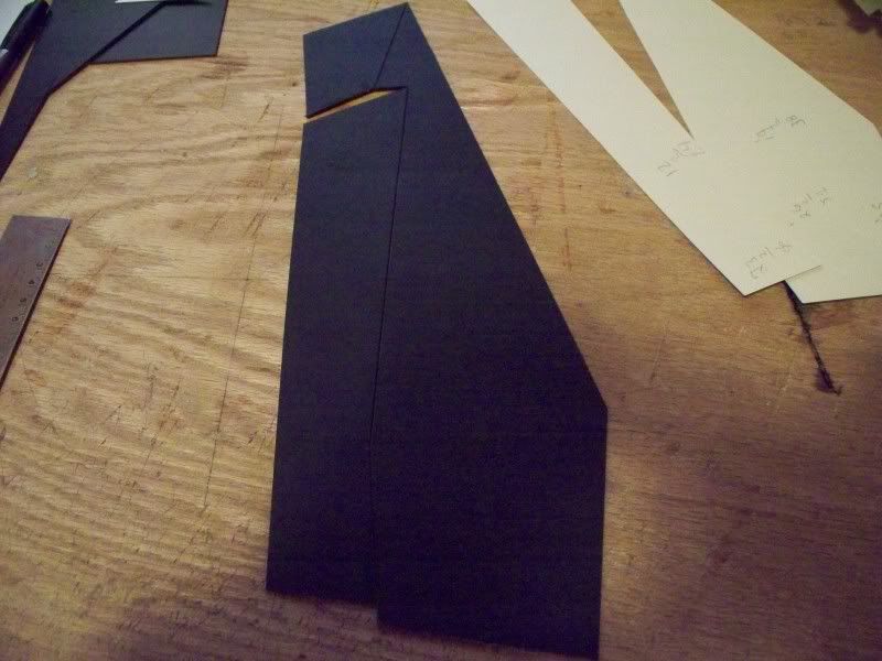
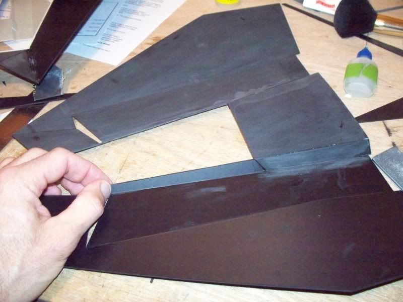
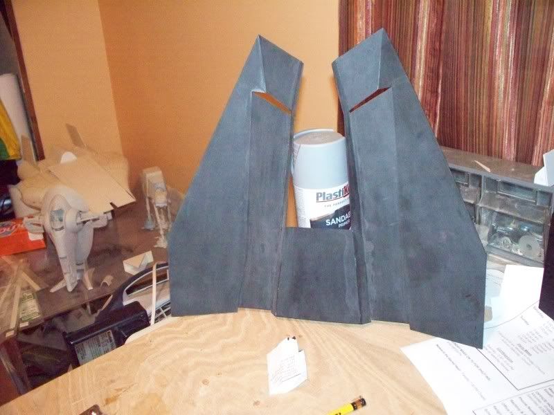
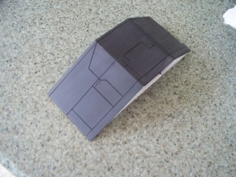
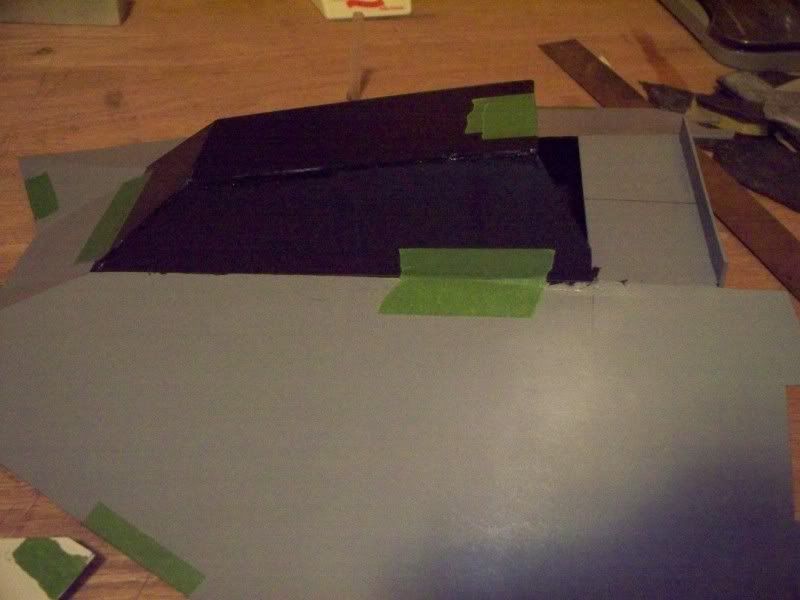
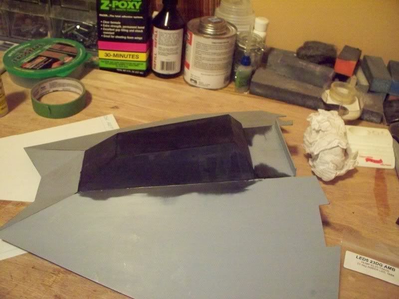
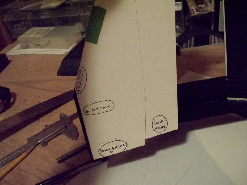
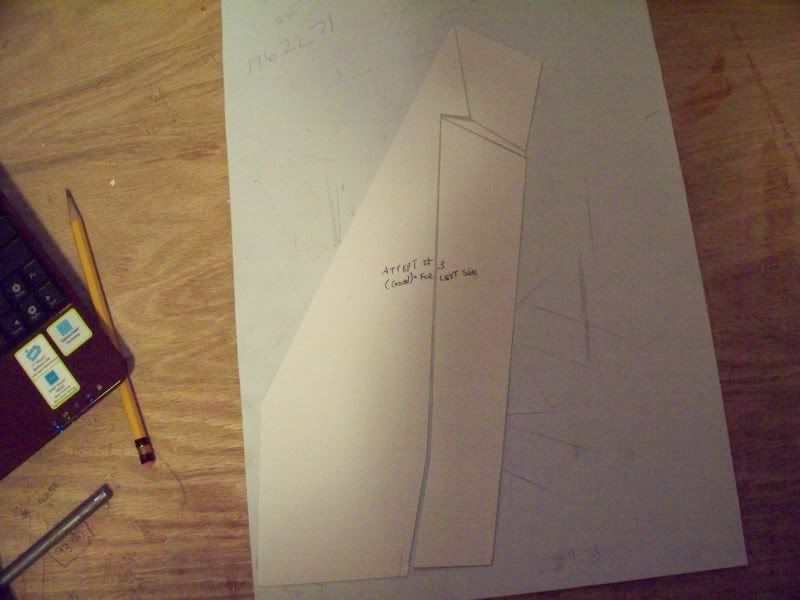
Moving along taking measurements and scaling them up
to have a decent looking template....
100_3191.jpg


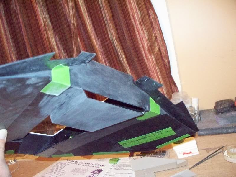
Did the above templete fit......NO and i knoew it
wasnt going to!LOL But as you can see i took some
corrective measurements and left the notes on the 1st
attempt.
100_3192.jpg


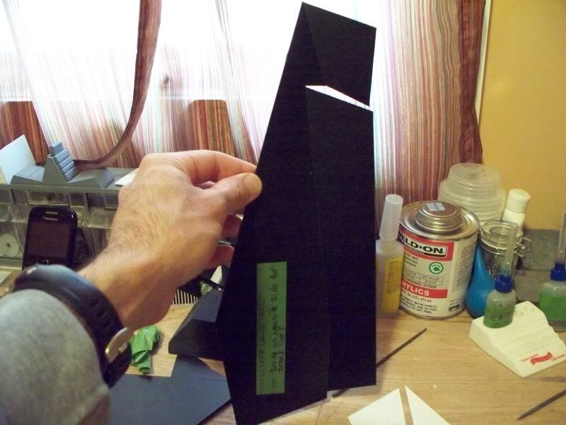
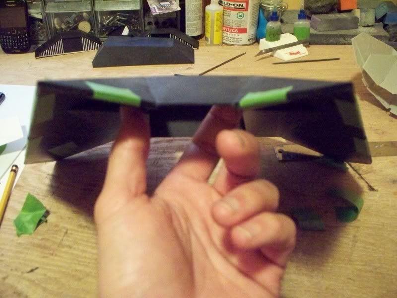
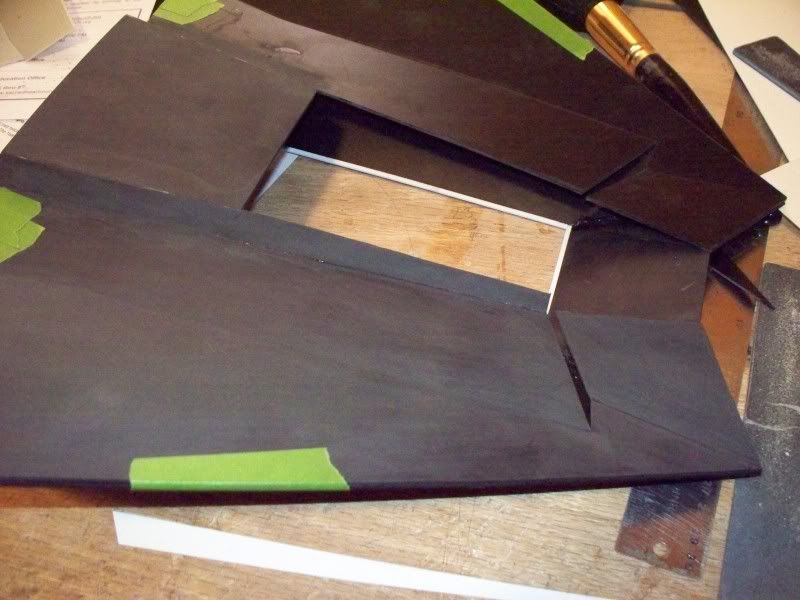
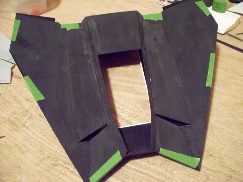
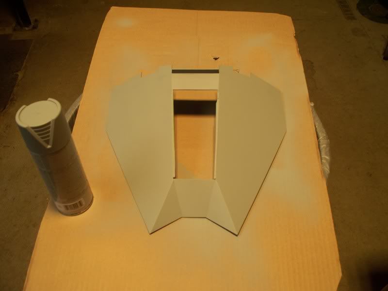
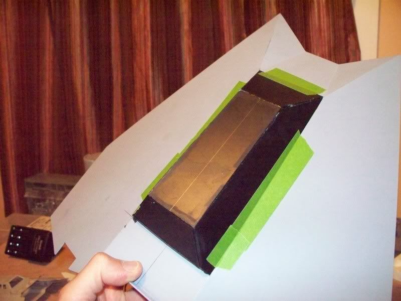
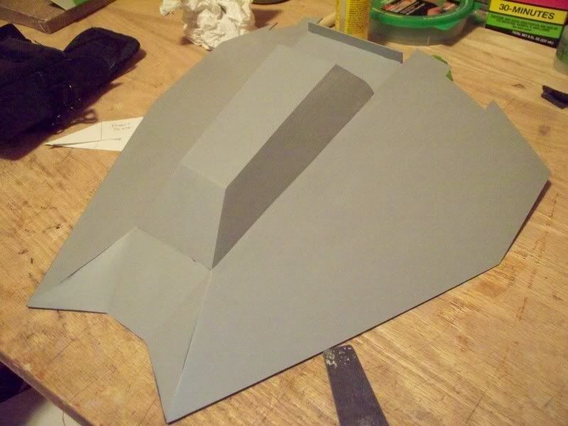
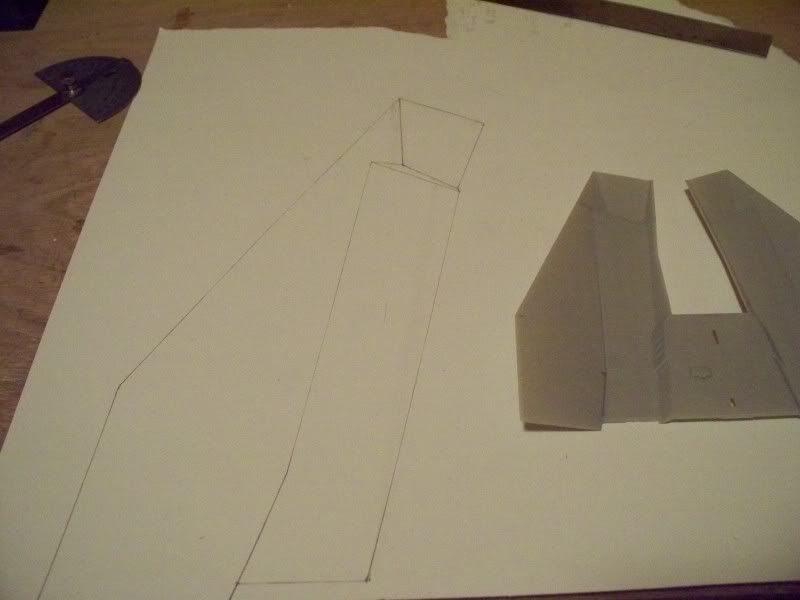
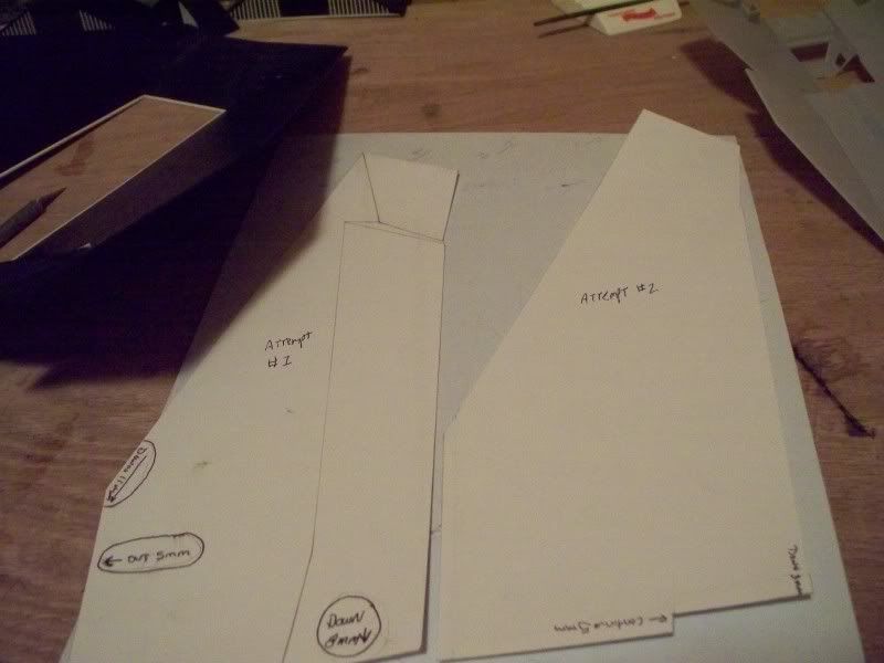
Ok 2nd attempt did that work.........ah No but again
dialing it in, again you can see the notes for change
only 2 this time!!!LOL
100_3193.jpg


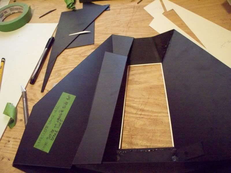
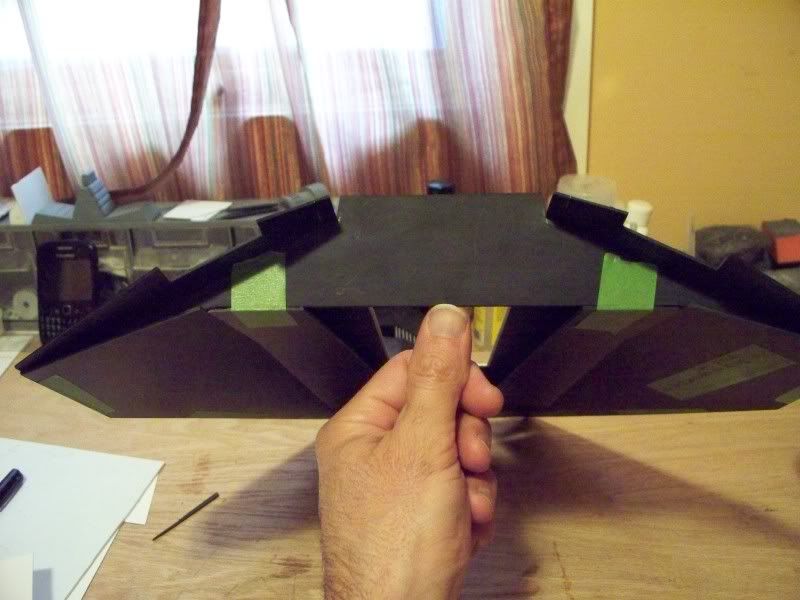
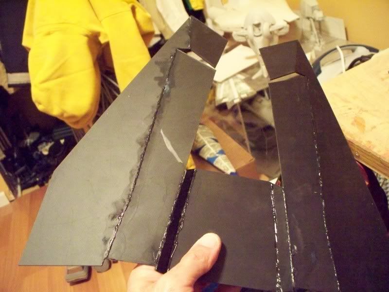
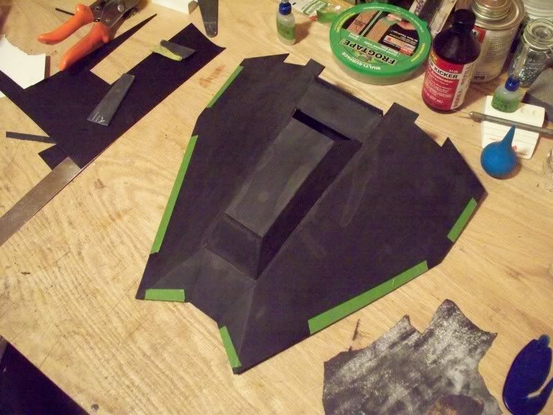
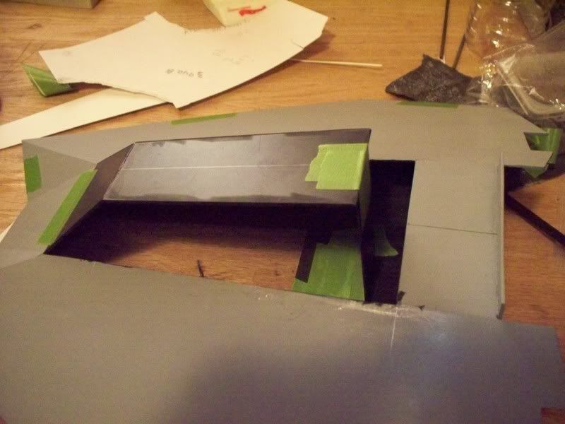
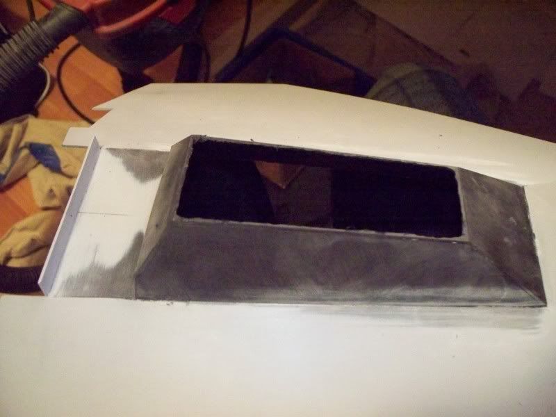
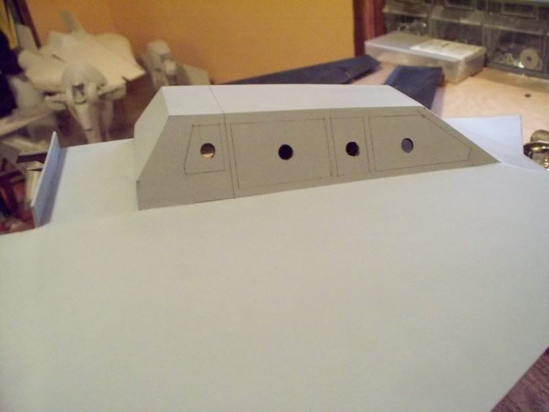
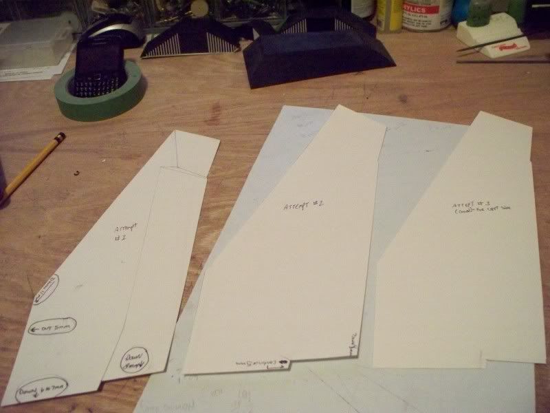
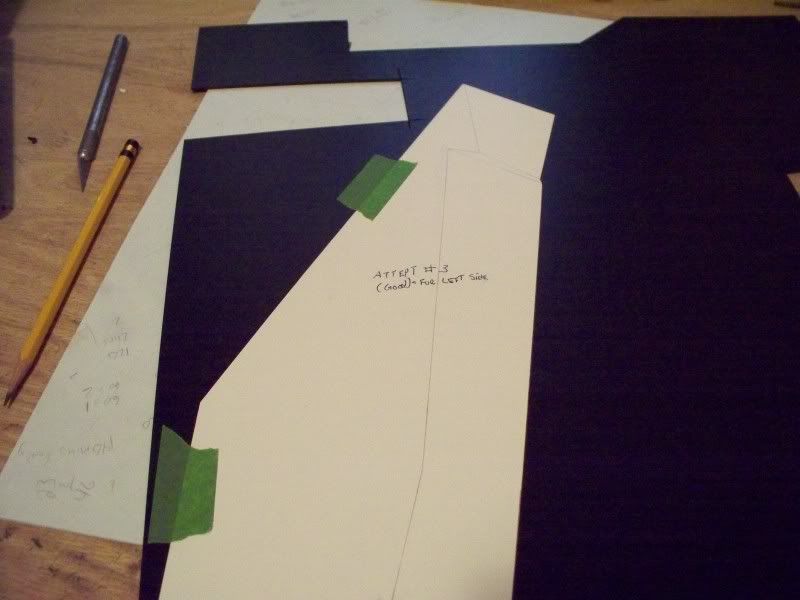
The 3rd attempt is good 3x's a charm must be something
to that saying eh?:lol Personally i think 1st time is a charm
but ......hey!
100_3194.jpg
 
Tape the template down it works better, and frees up your hands fromt muti-tasking while marking then you can outline it.
Llittle tip: Draw your template on the glossy
side of the poster board, the tape will come off much easier
and wont rip.:thumbsup
100_3195.jpg


After the template is drawn on the poster board,
i went ahead and cut up the template int useable
pieces.
100_3196.jpg


The cut template is used to mark the location of
the different sections on the plastic part.
I left a note to myself to re-apply the same
lines from the cut up template to the opposite side
also. Because the opposite side is where the break
lines will be opened to allow the hull to angle corrctly.
To many times i have drawn them on the wrong side and wasted
the plastic after scribing them!:angry:thumbsdown
100_3198.jpg


Ok this little piggy went to market and can't come home!:lol:thumbsup
Because it will not allow the plastic to bend while still in
place. So i just kind of .........cut it out of there! Plus I am not sure if the filming mini has these open or not? But i know one thing that plastic is not doing what i need it to do with it still in place!
100_3200.jpg


In this picture you can see the break lines, if you cut them to deep
you will cut through, or it will easily snap when trying to adjust.if you cut to shallow it will snap clean when you try to adjust. So how do you know when enough is enough? well as you cut or scribe them you will notice the plastic
starts to lift up on the clean edge from the cutting.Thats a good time to start thinking about "Not" making another pass with the old Exacto:thumbsup
100_3201.jpg


Here we go thr break lines worked well and i was able to adjust it,
those lines will be filled on the back side with the thick CA glue and get
a shot of accelerator.
100_3202.jpg


Ok here is one side... as you can see with the break lines
opened, i was able to adjust it to fit the power generator
bulkhead, that is glued to the top hull.This also allows for
a seamless joining on the lower hull as the glues is on the back
side. Thats it for now off to make the other side, then see about the middle section.
100_3203.jpg
 
Last edited:
Well here is the other side......
100_3207.jpg


As you can see the front of the lower hull is
to long i knew it was going to be. I didnt
make any adjustmants here, I figured nothing
is going on at the front, so i could just terminate
it there by cutting off the excess.
100_3205.jpg


Here is the front showing it
trimmed off.
100_3206.jpg


Rear view.......
100_3208.jpg
 
Hey Mikey... this looks awesome... I built a 3 footer out of mat board about 20 years ago so I know exactly what you're going thru for all the angles on the lower side... I think I went thru about 4-5 templates myself before I got it to fit just right. In retrospec thou I should have used styrene sheets but I was alot younger and there weren't any good sources of it around. Great work so far... cant' wait to see how it will look when its finished!
 
Thanks guys a little more progress on this.......
Started working on the center section to tie
the to halves together.

Template for center section, actually i made
the sides first but that pic would load, if I get
it to will post it.
100_3212.jpg


Center section glued to the sides....
100_3213.jpg


100_3214.jpg


Underside shot showing the open lines kind of
looking spot welded with CA glue. Even though that
doesnt show i sanded it all down.......just looked
nasty!LOL
100_3215.jpg


Still have to build the tub and detail it so halves
will stay separate for now.
100_3216.jpg
 
Thanks guys!:thumbsup

Started on those runers that go from the back,
up to the front of of the nose......
001-1.jpg

004.jpg

002.jpg

100_3223.jpg

100_3226.jpg

100_3237.jpg


I went ahead and built another canopy and started to
attatch it still need to finish up the back.This one fits better,
plus i needed a braek working on the bottom hull......that
was getting on my nerves!:lol
100_3247.jpg


I will start to scribe the panle lines on the rear boxes
and build in the toe pockets. A nice break from the bottom
of the speeder, which still needs the air ram to be built.
 
Well i went to draw the lines for the windows
to cut them out, when i got to the front window
something was looking really weird.:lol The top
should be 40mm i had it at 50mm some how!:thumbsdown

It effects the top and then the sides so i had to
make another canopy this also effects the rear boxes,
because the angle of the canopy is different where
they mount. So will need new rear boxes also, that's
ok because i want to scribe the panel lines this time
before i cut them.

I did make another canopy today..........
 
WOW I am all over the place with this thing!:lol

I did get another canopy on there and still got
it a bit to high at the back! So I had to dremel
off the top and bring it down, then cut out another
top!:unsure:thumbsdown

100_3264.jpg


New canopy which ended up being to high.......
100_3265.jpg


100_3266.jpg


100_3267.jpg


100_3268.jpg


:angry This is where I had to dremel off the top to drop it.
100_3269.jpg


Cleaned up new top ready......
100_3271.jpg


100_3272.jpg


100_3273.jpg


This is interesting the kit has the window frame very thick,
i dont like that so i trimmed the thickness of the frame from
about 8mm to around 3.5 mm-4mm Problem is it has an effect
on that small window at the rear. That window has to almost but
not quite meet the tab on the rear box. So i had to make that rear
window longer than it should be.Pilot holes for dremeling out the
majority file for the rest and corners.
100_3274.jpg


100_3276.jpg
 
3d, this turning out awesome. That is a ton of pain staking work but it really shows. Great job. I also love the detailed explanations of what you are doing and how you are doing it. For a novice like me, I find the " how to do this" information very informative and helpful. Thanks and stay with it.
 
This thread is more than 12 years old.

Your message may be considered spam for the following reasons:

  1. This thread hasn't been active in some time. A new post in this thread might not contribute constructively to this discussion after so long.
If you wish to reply despite these issues, check the box below before replying.
Be aware that malicious compliance may result in more severe penalties.
Back
Top