Scratch-built Space Tug (another go)

JCalhoun

Active Member
I’m starting, again, to try and build a Space Tug model from scratch.

The space tug was one of those things that NASA and other space visionaries in 1970 believed the U.S. would have as part of its regular space fleet — sometime before the 1980’s, of course. (Below: the green line was roughly where NASA was when I came across this in a book as a kid, the space tug is circled in red.)

space-flight-evolution-1.gif


When I was a kid growing up in the 1970’s I would occasionally come across depictions of this quirky utility spacecraft in the various books about space that I would check out from the library. Always some artist’s concept of course since it never saw the light of day. Damn, but I wish there had been a plastic model of that space tug when I was a kid.

space_tug_elements.jpg


And so my hobbies as an adult, it seems, focus more and more on creating some of those things that I wish had existed.

Space Tug Eath Orbit Applications (1024 x 718).jpg


Some years back I made an effort to scratch-build a space tug using what you might call ILM techniques (acrylic substrate, lots of styrene, greebly details). It started out okay but I lost some of my initial enthusiasm as small problems crept up. (I posted my aborted attempt here.)

With 3D resin printers having become affordable and able to reproduce such fine detail, I thought I would have a go at creating a space tug again. This time though it would be without acrylic, styrene or even greeblies. I was going to try and model it all in Blender (the open source application), 3D print it in resin.

Sometimes too when I start on a project the goal is as much to learn new skills and gain some new knowledge. If a space tug model results, that’s excellent. (And I have often learned plenty even from the abandoned projects.)

If some of you have mastered CAD programs, that’s cool. I know Blender is not a CAD app, was not intended to be, but the price was right (ha ha) and learning Blender was one of those new skills I was hoping I could bundle into this project. (And hey, Blender can also handle sculpting, animating, rendering if I should wish to expand to those areas later.)

space_tug_crew_module.jpg


And yeah, since a space tug is more or less a cylinder with windows and a couple of manipulator arms, it seems like a pretty reasonable project to wade into both Blender and 3D printing as well.
 
I decided to build the space tug at 1/48 scale. Since apps like Blender specify models with math and geometry (not pixels or voxels) there is not really a “scale” built into the model so to speak.

But for practical purposes I chose a scale.

A determinate scale allows me to know when to stop adding detail to the model. Should I add toggle switches on the control panels? (Thankfully, no, they would be only a small bump about ½ millimeter in size in the final print.)

As another example: knowing the target model size allows me to find a reasonable thickness for the walls and other structural parts of the model. You can make the walls as thin as sheetmetal in Blender (and maybe that is in fact what the actual spacecraft would have had) but try to print that at 1/48 scale and see what a mess you get.

The point about wall thickness, and the final size of the model brings up another issue. Since in modeling and printing of the space tug there was to be a lot of trial and error, I started out pretty slowly. I did not rush into adding detail before I knew in fact how thick to make the walls.

iterating.jpeg

Above you can see the incremental experiments to determine size, wall thickness (starting at the top-left). Eventually I start to arrive at the basic shape breakdown.

My first week of designing/printing was pretty much just printing cylinders, later “lids” for the cylinders.

Though I soon found the sort of minimum ideal wall thickness, the next quandary was in how to decompose the model into individual components that could be printed separately, painted separately, and then assembled to create the final model. I think everyone here understands that you would not want to design a monolithic model that had an inaccessible interior — you couldn’t light the interior, couldn’t paint the interior….

design_print_iteration.jpg


So it was only after a number of rather droll experiments that I very slowly allowed the space tug design to start to take shape, start to look in fact like the 1970’s NASA images.

misaligned_print_1.jpeg

Above: model shape-decomposition fail. Under the best of circumstances these two parts will probably never line up.

One of the hard realities of 3D resin printing is that resin shrinks (to varying degrees — I understand the real expensive stuff shrinks less but it’s outside my budget). Shrinkage turned out to be a huge factor in guiding me in determining how to decompose the model into parts. A few early experiments made it clear that there were definitely wrong ways to do it.

misaligned_print_2.jpeg

Above: a failed space tug body experiment as seen from the side. Again, a worst-case scenario, but still I would never break something like the smooth body of the space tug into pie-segments for 3D printing. It's just not going to work.
 

Attachments

  • design_print_iteration.jpg
    design_print_iteration.jpg
    35.2 KB · Views: 85
Last edited:
If it were easy everyone would be doing it!
Thanks. Hopefully I can make it a little easier for those wanting to venture into creating your own models from scratch. Keep you expectations in check — hobbyist 3D printers are not going to put Bandai out of business any time soon. But it is fascinating to see how far you can get with these little machines.

Another issue I ran into when going from Blender to print involved curved surfaces like the major cylindrical body of the space tug.

Blender is not purely “mathematical” I suppose in regard to curved surfaces since, at the end of the day, cylinders are still represented as a number of polygons joining 3D points specified in space. So a cylinder is not in fact curved but instead more of a polygonal prism. There are smooth shading algorithms that Blender can employ to make the cylinder look nice when rendered within the application, but the output is nonetheless going to be faceted.

Your only control over this, that I have discovered, is to be smart in specifying the number of segments (facets) when creating the cylindrical shape. And here, again, is where the resulting scale of your print should be your guide.

Over-specifying the number of segments to make up the cylinder will make it slow to render and manipulate in Blender. (And if you end up having to go in and hand-edit vertices like I did, obviously the more there are, the more tedious this can be.)

Under-specifying the number of segments will make the resulting print look … prismatic, not smooth.

So, again, the early experiments that I showed a photo from were also used to arrive at how many segments should I go to in order to get a smooth-enough cylinder. (You could also do math to figure this out — knowing the resolution of the 3D printer you are using — but I guess I trust the resulting resin rather than the math.)

For what it’s worth, 1024 segments (I have a programming background) looked reasonably good to my eye for the large cylinder. For smaller cylinders I would scale proportionally down from that. (There is no need of course for a manipulator arm, which is maybe one-fiftieth the diameter of the space tug body, to also be composed of 1024 segments.)
Subdivision is the key to your faceting issues. I am a real-time 3D artist for a living so while CAD would be better,I don’t model that way and use polygons. I am a Max user but all modern packages do Sub-D
 
Subdivision is the key to your faceting issues.
Blender does have a subdivision modifier but it is not clear to me that it persists in the geometry when you export the model as a 3D file. I should experiment with that.

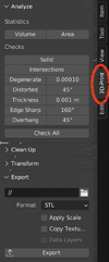
I should have pointed out earlier, I am using Blender's built in Mesh: 3D Print Toolbox to export STL files (for the 3D printer's eventual consumption).

3Dprint.jpg
 

Attachments

  • Screen Shot 2023-01-22 at 10.00.31 AM.png
    Screen Shot 2023-01-22 at 10.00.31 AM.png
    275 KB · Views: 101
The exterior of the space tug is, as you can see from the artist renditions, basically a cylinder. As I have started feeling my way around in Blender I have come to find that, perhaps unsurprisingly, there is more than one way to create a cylindrical shell model.

Without diving into a Blender tutorial (YouTube has plenty of those) I’ll give you two ways to create a simple cylindrical shell (and yet there are many others).

Exterior0.jpg


One way is to create a cylinder matching the outside diameter of your model and then create another cylinder that corresponds to the inner dimension of your model (above). There is a modifier in Blender then called Boolean that will allow you to subtract the second cylinder from the first. That is, from the outer cylinder, remove the volume corresponding to the inner-sized cylinder.

Exterior1.jpg


If you have any sort of capacity to visualize this operation in your mind you will realize that you will be left with a tube — exactly the desired shape. If there is any challenge here it is determining the size of the inner cylinder that will leave you the desired wall thickness for your “tube”.

Exterior2.jpg


A second way to create a tube is to, again, start with a cylinder the size of the outer dimension of your model and then go into Blender’s Edit mode and remove the top and bottom face of the cylinder (above). This leaves you a cylindrical “skin” with no thickness whatsoever. But then back in Object mode in Blender you select the Solidify modifier. The Solidify modifier lets you specify a thickness and then computes the resulting shape that has that thickness.

Exterior3.jpg


Both methods above give you the desired tube object, but from different routes. Since both are modifiers (in Blender parlance) they are computed properties and are not “baked in” but remain dynamic. That is, weeks later if you should choose to, you can shrink the inner cylinder that was used to “cut” the outer cylinder (in the first example) in order to thicken your walls.

Or you can, weeks later, change the thickness of your Solidify modifier if you also should decide to change the wall thickness. In this way, there are “CAD-like” aspects to Blender.

The downside of the dynamic modifier though is that the additional computations start to add up and make Blender perform more and more sluggish. How cutting edge your computer hardware is will determine how many complex modifiers you can chain together before the user interface becomes … unusable.

For the above reason, I chose to Apply (or bake-in) the modifier that I used to create the cylindrical tube fairly early on. (This of course was not done until at least one actual resin print was made to confirm the wall thickness was something I could live with.)
 
In max subdivision is within the edit poly properties rather than an added modifier,Hence it is retained when exported. Max is expensive but it has really good modeling tools. All 3D packages can have a steep learning curve,which is why I have used max my whole career. I love seeing people 3D model!
 
I love the disk tug.

A manned Pye Wacket might be next:

Phillip Bono had a highly notional HLLV saucer design—meant only to show how ROOST was the simplest design. Yet he would not have drawn it if it wasn’t do-able…basically a flatter Big Onion:

 
I said I didn’t want this to turn into a Blender tutorial but it’s probably useful if I call out at least a few of the things I latched on to when using Blender so that others might skip a lot of the dead ends (or tedium) that I first tried.

Your approach certainly should be to first perform large shaping operations on your model.

At this point my space tug is nothing but a simple cylindrical skin. Which would you tackle next on the model? Panel lines? Bad idea — that kind of detail should be the some of the last operations you do to the model.

Instead, gutting out a large opening for the windows would be a good next step. In this way, like a sculptor with clay, you rough in the shape — only moving down to the small details at the end.

I mentioned the Boolean modifier in Blender previously as a way of hollowing out the cylinder. For cutting out holes in shapes the Boolean modifier has proven invaluable. And so it was ideal for “window letting”.

Creating a “pie” shape is another one of those things where there are no doubt countless ways to accomplish this in Blender (I explored several). Since a wedge is pretty specific to the space tug though, I’ll skip over the process I settled on. What follows though is the result.

cylinder_and_wedge.jpg


The wedge above exists only to act as a "cutter".

cylinder_minus_wedge.jpg


Once the Boolean modifier is added to basic cylindrical body with the wedge object subtracted, the result is what you see above. At this point you hide the wedge object (as I did above) since its role is only as a "procedural object".

Hopefully you have a taste of the small steps you take in Blender. I'll skip over the other steps for the exterior component and just show you where I ended up.

exterior_final.jpg


And resulting resin print:

printed_exterior.jpeg
 
I decided to try a design for the space tug that featured a kind of “arm box” beneath the cockpit windows (you can see the cut-out in the previous photo). Something a lot like the front of R2-D2, just below his dome. My thought was that the arms could retract into this compartment and the outer cylinder of the space tug would be flush when launched (either on top of a rocket stack or in the bay of the space shuttle).

Initially the recess for the arms was integrated into the cylindrical exterior of the space tug, not a separate printable part, but I kept running into issues trying to support the inner surface of the recess. Many of the resin prints failed just in the “upper lip” area of the space tug exterior. For that reason, I made it a separate piece.

armbox.jpg


This has the added benefit of making it a little easier to paint the recess a separate color from the exterior of the space tug.

I stopped adding detail to the "arm box" at some point, but could certainly go back and add more. The two rectangular holes are to receive the manipulator arms (coming).

armbox_printed.jpg
 
The interior was to be, obviously, a separate printed part. This would allow me to paint it.

The interior of the space tug is one place I could have gone crazy adding detail — just have a look at the interior of the actual Apollo Lunar Module to get an idea of another machine that would have been of similar pedigree . At the same time the interior is going to be barely once the space tug is assembled.

In the end, iteration fatigue is probably to blame for my settling for a minimal of interior detailing.

interior.jpg


It didn’t stop me though from obsessing over how I might represent in Blender a floor for the space tug that looks like the triangular-lattice structure that the Skylab space station employed. When thinking about the space tug details I tried to look for other spacecraft from the era (early 70’s) and imagine what elements I could borrow.

By the way, this might be a nice piece of the space tug where I can point out two other modifiers in Blender that I made use of.

Since there are three walls, with 120 degrees of rotation between them, I made user of the Array modifier in Blender. It allowed me to create a single wall but then assign a modifier to the wall object to specify that I wanted an array of them. I set the Array modifier count to 3 and specified that each wall be rotated 120 relative to the previous one. (Creating the three overhead displays also made use of the Array modifier).

The other Blender modifier I used quite a bit is the Mirror modifier. There are, as you can see, two closets or alcoves on either side of the central airlock cylinder. I only had to model one of the closets, apply a Mirror modifier, and Blender took care of creating a the closet on the other side of the interior.

View attachment 1662033
 

Attachments

  • printed_interior.jpeg
    printed_interior.jpeg
    317.7 KB · Views: 97
There are clusters of small rocket motors around the perimeter of the space tug (as there was on the Apollo service module for reference). These of course are to rotate, translate the spacecraft when maneuvering and are often just referred to as the RCS (reaction control system).

While I could have integrated the RCS into the exterior part of the space tug, I decided to have them print separately (to be glued on later) for a couple of reasons. Painting the exterior would be more challenging with these little rocket packages around the circumference. And also because I suspected the RCS pieces would be fragile and may break off (rather than gluing them in place, I am going to experiment with attaching them with beeswax — we'll see how that works out).

And here’s another case where my chosen 1/48 scale came into play. The initial RCS motors I made in Blender looked like a good size for the model. Printing them though gave me a little partially formed thing. :( The overall size was simply too small and really pushing the limits of the 3D printer. In addition the walls of the rocket bells were simply too thin.

So I went back into Blender and scaled up the RCS object — and in particular made the rocket bells beefier.

rcs_blender.png


Even so, I think I ended up with little RCS prints that are on the lower end of how small I would try to print a thing.

rcs_printed.jpeg


Clothespin for scale:

rsc_detail.jpeg
 
The manipulator arms, as I mentioned, are a departure from the artist’s concept of the space tug. In order to get them to fold neatly in the small space beneath the tug window I wanted to make them have some curve as well — curve to match the radius of the space tug exterior.

Like the RCS clusters, the arms were getting kind of small in size for 1/48 printing in 3D. I wanted some detail though so I added what I imagined were cylindrical motors partially revealing themselves at each joint.

Additionally, I added a feature that would resemble gearing. Having these little recesses and bumps suggests detail, gives something for a paint wash to cling to.

arms_blender.jpg


Originally I imagined the arms to be posable. Having become familiar with the tolerances of resin printing (or lack thereof) I decided to try using tapered, cone-like joints. The parts would not hold together on their own however but I could still “pose” the arms and then hit each joint with a drop of CA glue to secure them. Eventually though I decided that what I preferred was to “pose’ the arms in Blender and print each arm as a single pre-posed object. I did both a left and right retracted arm and a left and right extended arm.

arms_printed.jpeg


Again, like the RCS, Im going to try to avoid permanently gluing these to the model as I expect them to eventually break off (well, the extended ones anyway). So, again, I am going to see if a little beeswax can be employed to keep the arms in place but allow replacement if the arms break.
 
What follows are the remaining bits that make up the space tug. (I am working on a stand as well but am so far unhappy with the results).

tug_ceiling.jpg

The ceiling is a little pie slice thing (above). It also could stand more detailing but is barely visible inside the space tug. Besides the two cutouts for windows in the ceiling the only other noteworthy feature are the pair of overhead wedge-shaped boxes. Originally I thought they might house controls but they seemed to be a better place to house LED lighting to illuminate the interior of the space tug.

tug_bottom.jpg

Above are two components — the very fluted bottom of the space tug and a separate docking hatch. The hatch will be removable so that the space tug can instead sit on a stand that will be designed to plug into the hatch opening.
The fluting was a nod to some portions of the Saturn V rocket where there is a similar manifold-like structure — presumably to add strength. Yes, the flutes were made a lot easier using the Array modifier from Blender.

tug_top.jpg

And finally (above) the top of the space tug. You can see the corresponding pair of windows that allow the occupants of the space tug to look out (for docking, no doubt). The ribs and concentric rings are suggested in some of the artist's concepts for the space tug from that era.
A duplicate docking hatch is to be printed to fit in the central hole above. (And, again the Array modifier for the spokes, Mirror modifier for the window cut-outs.)

A few printed parts:

ceiling_printed.jpeg


bottom_printed.jpeg
 
One benefit from all the iterations that I have 3D printed is that you have plenty of "bucks" to try out various painting techniques and paint schemes on. Since I am new to airbrushing (well, painting models generally) it was useful to be able to try a number of sometimes seemingly radical techniques and learn from them.

Here was one process for painting the exterior.

exterior_masked_1.jpeg


I regret having used blue-tape as a masking "filler". It sometimes took the underlying paint off. Never again.

exterior_painted_1.jpeg


Now to under-paint other panels.

exterior_painted_2.jpeg


"Come on, get happy!"

exterior_painted_3.jpeg


Taking it down with an off-white.

exterior_painted_4.jpeg


Painted the "anti-glare" panel surrounding the windows a magnolia brown (not black).

armbox_painted_1.jpeg


The "arm box" is a simple zinc chromate green. Seemed like something the aerospace industry would leave on interior portions of the space tug.

exterior_painted_5.jpeg


The final paint job of the exterior (above) — seen next to a virgin print.

Using a vinyl cutter with a very-70's font, I added a large red number to the side. The arm box is CA-glued in its place.
 
Last edited:
With that angular look—I could see it as a Star Wars control tower with a laser battery up top.

Now, if I am not mistaken, the last trilogy ALSO had the Millennium Falcons engine strip insert at a similar angle:

I could see a pure disk with your tug front joining with the Falcon engine strip behind as a people mover…no B-36 type cockpit…just a pure disk.
 
Last edited:
The interior was next up.

This part could have been made easier to paint if I had broken it down into separate, printable sub-assemblies. I decided though that if I could figure out a way to paint it, I would leave it as is. As it turned out, I was only barely able to paint it as a single part. In fact, the result was poor enough that I am thinking that if I open this up for another iteration, I will probably try to at least make the hatch a separate printable piece.

interior_painting_1.jpeg


Above, a darkish grey is applied — primarily focused on the interior "closets", the floor and the faces of the three overhead control boxes.

interior_painting_2.jpeg


The closet rear walls were masked with custom cut shapes using a vinyl cutter as was the floor (the vinyl mask is still in place above) and also the faces of the three overhead control consoles. Then I hit it with a light grey — focusing on the hatch, closet interior and bezel, and the three overhead control boxes.

interior_painting_3.jpeg


After the light grey had dried, I attempted to cover the hatch with silly putty (above) and mask off the three overhead control boxes. The floor remains masked off. Also, I used another mask cut from vinyl to mask off the closet and bezel.

interior_painting_4.jpeg


And above is the result. It is on the plain side and the masking did not go perfectly. I remind myself though that you will not see much of it once the space tug is assembled. (And there is always 2.0.)
 
Can I give you some masking tips for airbrushing?
The blue tape peeled your paint off (probably) because there was an oil on the surface that prevented the primer from adhering. You can avoid this in the future by washing your parts before you paint them. Some people use rubbing alcohol, but I scrub all my parts with degreasing dish soap and a soft toothbrush. Once it's washed, try not to handle it with your fingers, or wear gloves, so you don't get oil on it again.
Another trick you can use is to stick the tape to the back of your hand a couple times to remove some adhesive before you stick it to your model.
Do both of these things, and you shouldn't have any paint coming off with your tape ever again.

That said, your paint job looks great. I'm enjoying watching this come together.
 
Back
Top