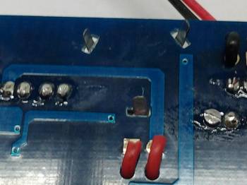
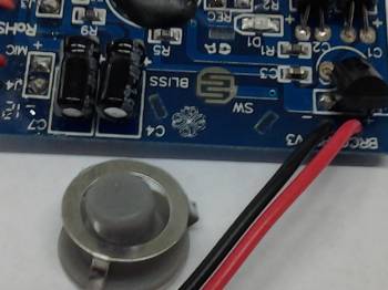
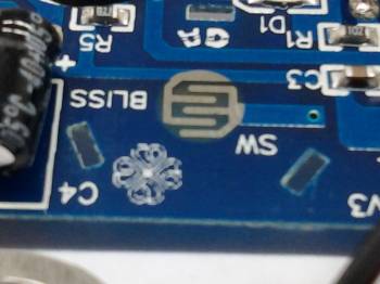
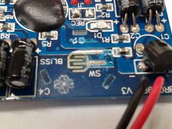
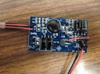
I had this years ago too. If you open it up, (There are no screws, just some plastic pillars to clip both sides of the badges together) inside it is a very simple circuit board that houses two LR44 batteries (I think) and a black blob. Yep, its this black blob which triggers the less than 1mm thick piezo sounder to 'click'. And the effect, although is not the sound of an actual Commbadge but its quite close enough for me.
If everyone were to use this same approach, then there is no problem except that the thickness of the batteries must be considered and again, it would have to be a two-piece badge since the piezo needs to be on a flat surface. But I am very confident no one minds if the thickness extends by another 3mm or so. Plus, you need to 'push in' to the badge to activate a switch.
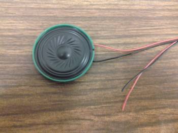
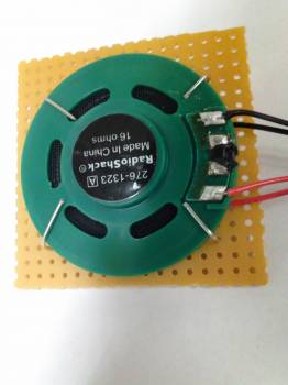
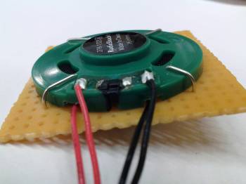
majenko's board is quite good and his solution is to take an actual sound sample (which you can get from the Generations Soundtrack CD) and play it. Because he is using a dsPIC, I am sure majenko would be able to get some codes for capacitive touch sensing. But the real problem here would be a speaker small enough to go inside the badge and still be able to have the sound heard, say, within 2~3 feet. And batteries, yeah, its taking up so much space, even for a more 'common' cheep and cheerful LR44.
So, here is my idea, which could be possible for both TNG and Voyager Commbadges:
1. Make the Commbadges in hollowed out metal but with tiny rectangular slots around the delta arrow for sound. The interior would also serve as an echo chamber.
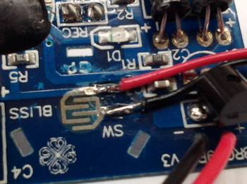
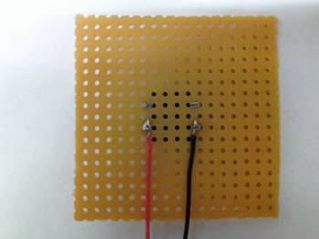
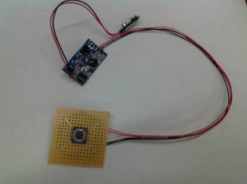
2. Attach a wire to the badge from a PIC chip that has capacitive touch sensing capability.
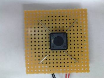
3. Attach a piezo sounder to the chip. (This eliminates the need for an amplifier)
4. Program the chip to 'chirp' the piezo sounder when there is a 100ms tap. Any longer than that, it would not sound (because chances are, you're holding it).
5. If there are no 'taps', go on standby/sleep mode to conserve energy.
Possible problems:
1. For the TNG, this design is effectively the same as the QVC and so, looks quite ok. But for the Voyager, we would need to increase the thickness more due to the electronics and batteries.
2. Both also needs to have a base and so, again, the QVC two-piece design is the blueprint for this.
3. I really, really, do not have the resources to do this since my programming sucks and I only know how to light up LEDs. :lol
4. When its ready, Shut up and take my money:behave


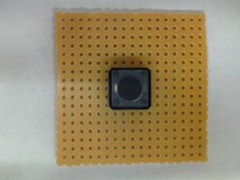
") As long as it's bigger than 10mm x 10mm as that's the smallest my PCB suppliers (and most PCB suppliers) can do.
As long as it's bigger than 10mm x 10mm as that's the smallest my PCB suppliers (and most PCB suppliers) can do.