Yutani Exec
Active Member
Whilst there has been much time and effort, and discussion, focused on the identification and sourcing of the K-Type dinghy quick release hook greeblie found part, the back pack antenna is currently the part that is proving the most enigmatic.

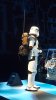
These observations are based upon details associated with the Rogue One Stormtrooper (R1 TK) back pack as seen on display at Celebration Europe 2016 (CE) in London.
Antenna – Found Part Identification and Reveal
The observations are from a small team that has been exhaustively looking at the CE back pack (myself, mr paul, lonepigeon and ht7) and this post will present an examination of the antenna prop whilst comparing it with what the team now believes is the found part. We will focus on diagnostic features seen from the CE reference material.
Originally there was a hypothesis that the antenna is an altered / modded military radio antenna, as used on jeeps, Land Rovers etc., ‘Telefunken model Ms 116/117/118’. Discussions also looked at the possibility that the antenna is a fishing rod. The ‘eyes’ / guides that the tubing on the antenna is threaded through were rapidly agreed to be fishing rod line guides (hereafter referred to as ‘eyes’). We will look at these in detail further down.
The team has discounted the use of a military radio antenna as the prop. This is based on the diagnostic features listed below, and also relates to the relative rarity of these parts and their prices; most examples fetching prices in excess of £50 and up to £100+. This did not seem to be the type of part that is used by Star Wars prop builders, for what will effectively be background props. As we know from experience such items in the OT were built from cheap items such as seed trays, plumbing parts, Tupperware and wet wipe tubs e.g. the sandtrooper packs I in Episode IV. The prices did not stack-up for us.
Detailed review of the available reference pics has convinced the team that a fishing rod was used for the prop – a common and generally cheap part to source for prop building. The reference material shows several distinct diagnostic features that we have used to identify what we believe is the found part. These diagnostic features are:
1. Texture of the antenna;
2. Details of the cut end;
3. Antenna outer diameter;
4. Details of the eyes and their spacing – this also relates to antenna length; and
5. Eye whipping / ‘wraps’ and the red ‘flash’.
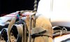
Texture
The CE prop antenna has a distinctive texture that appears to be a type of black carbon fibre wrap. The carbon fibre has a rippled texture running around the antenna and is evident on a lot of modern fishing rods. This observation is based on referencing online pictures and also personal observations made by team members looking at rods in angling and outdoor recreation shops. The pictures below show the CE prop and then the found part.


Open (Lower) End of the Antenna
There are several reference shots of the CE prop that show the bottom end of the antenna. From the reference material the antenna appears to be hollow with a grey colour associated with the end.

When the found part fishing rod is cut it gives the same appearance as the CE prop.

Antenna Outer Diameter
We have taken guestimate measurements from the CE antenna. These have been determined using the known width of the webbing used on the canvas roll as reference. The webbing is standard 25 mm / 1”. A marker line was drawn on a reference pic and then transferred to the cut end of the antenna. The outer diameter (OD) of the cut end is approximately one-third the width of the webbing i.e. 7-9 mm as judged using the reference pic. This was the OD range we were initially looking for. It should be noted that the reference materials make it hard to be specific as the lighting at the CE display is problematical and no clear flash photography could be found of this part.

Measurement of the found part shows that the OD at the cut end is 9 mm, so within the range we were hoping for from the picture calculations.

We also compared the found part with life-size zoomed reference pics to determine if we had a match. Again, the width of the webbing was used to establish a baseline scale so that the image was not biased by the width of the found part.

End Part 1 - only because of no of pics I can post - Part 2 will immediately follow...
Yutani Exec
These observations are based upon details associated with the Rogue One Stormtrooper (R1 TK) back pack as seen on display at Celebration Europe 2016 (CE) in London.
Antenna – Found Part Identification and Reveal
The observations are from a small team that has been exhaustively looking at the CE back pack (myself, mr paul, lonepigeon and ht7) and this post will present an examination of the antenna prop whilst comparing it with what the team now believes is the found part. We will focus on diagnostic features seen from the CE reference material.
Originally there was a hypothesis that the antenna is an altered / modded military radio antenna, as used on jeeps, Land Rovers etc., ‘Telefunken model Ms 116/117/118’. Discussions also looked at the possibility that the antenna is a fishing rod. The ‘eyes’ / guides that the tubing on the antenna is threaded through were rapidly agreed to be fishing rod line guides (hereafter referred to as ‘eyes’). We will look at these in detail further down.
The team has discounted the use of a military radio antenna as the prop. This is based on the diagnostic features listed below, and also relates to the relative rarity of these parts and their prices; most examples fetching prices in excess of £50 and up to £100+. This did not seem to be the type of part that is used by Star Wars prop builders, for what will effectively be background props. As we know from experience such items in the OT were built from cheap items such as seed trays, plumbing parts, Tupperware and wet wipe tubs e.g. the sandtrooper packs I in Episode IV. The prices did not stack-up for us.
Detailed review of the available reference pics has convinced the team that a fishing rod was used for the prop – a common and generally cheap part to source for prop building. The reference material shows several distinct diagnostic features that we have used to identify what we believe is the found part. These diagnostic features are:
1. Texture of the antenna;
2. Details of the cut end;
3. Antenna outer diameter;
4. Details of the eyes and their spacing – this also relates to antenna length; and
5. Eye whipping / ‘wraps’ and the red ‘flash’.
Texture
The CE prop antenna has a distinctive texture that appears to be a type of black carbon fibre wrap. The carbon fibre has a rippled texture running around the antenna and is evident on a lot of modern fishing rods. This observation is based on referencing online pictures and also personal observations made by team members looking at rods in angling and outdoor recreation shops. The pictures below show the CE prop and then the found part.
Open (Lower) End of the Antenna
There are several reference shots of the CE prop that show the bottom end of the antenna. From the reference material the antenna appears to be hollow with a grey colour associated with the end.
When the found part fishing rod is cut it gives the same appearance as the CE prop.
Antenna Outer Diameter
We have taken guestimate measurements from the CE antenna. These have been determined using the known width of the webbing used on the canvas roll as reference. The webbing is standard 25 mm / 1”. A marker line was drawn on a reference pic and then transferred to the cut end of the antenna. The outer diameter (OD) of the cut end is approximately one-third the width of the webbing i.e. 7-9 mm as judged using the reference pic. This was the OD range we were initially looking for. It should be noted that the reference materials make it hard to be specific as the lighting at the CE display is problematical and no clear flash photography could be found of this part.
Measurement of the found part shows that the OD at the cut end is 9 mm, so within the range we were hoping for from the picture calculations.
We also compared the found part with life-size zoomed reference pics to determine if we had a match. Again, the width of the webbing was used to establish a baseline scale so that the image was not biased by the width of the found part.
End Part 1 - only because of no of pics I can post - Part 2 will immediately follow...
Yutani Exec


")