Hi this is superb, you do amazing work. I would love to do this for my Pred suit. I see all the pics n details and is very helpful. First time doing something of this caliber but ready for the challenge. Do I need schematics and how do I know what wires to purchase?My late 2019 project I decided to take on was a Predator Costume like the one from the 1987 movie Predator with Arnold Schwarzenegger.
Updating for files I made/altered: Predator Armor - P1 Style - Hunter - from 1987 Movie Cut up for 8x10x8 Printer Bed. by moesizzlac
View attachment 1233578
Well not a 1/6th scale costume but rather a full sized one.
I can't make the costume perfect movie accurate because 1) I am no where near the height of the original actor who played the predator and 2) picture perfect is time and cost consuming. This costume was put together for under 500 I believe.
This build will be my version of a similar styled P1 Predator with as many bells and whistles as I can put together.
Like all things, we start with the planning. I went to the resources to get a bunch of Pepakura files to start converting for my project. Then I went to Thingiverse to see what they had and grabbed Predator Shoulder Cannon by makerslabcz.
After I had all the files, it was time to get to work and make everything printable. It took about a month in spare time to digitally fix everything up and resize it all to my body.
View attachment 1233579
The backpack:
This model was good for pepakura but not for a 3d print. I first ended up fixing the files and printing it out. This will be the shell to house most of electronics and power bank.
View attachment 1233580
View attachment 1233581
I only used half of this model from thingiverse and fitted it with a spot for a flashlight and a servo and an outlet for the wires to go out the lower back.
View attachment 1233582
View attachment 1233583
Both halves are held together with 8/32 screws and nuts.
View attachment 1233584
View attachment 1233585
Using this tutorial, I grabbed an Arduino Mega, an MPU6050, battery pack and wired everything up with 2 Cat 5 connections (One that goes to the helmet Where the mpu6050 will sit, and one to the left gauntlet for controls and sound)
View attachment 1233586
View attachment 1233587
This is a shot from underneath where the power switch is as well as the recharge port.
Left Gauntlet - Creation, sound and control.
Continuing with the planning, let's start with the pepakura file and add a hinge in the print so that it can flip up if I need it to. I also made a slot for my Phone below the flip plate.
View attachment 1233588
Let's allow holes for momentary switches and latching switches, cat5 connection and audio out on the flip plate:
View attachment 1233589
Now let's get it printed and loaded up:
View attachment 1233590
View attachment 1233591
View attachment 1233592
I wired it up with an adafruit soundfx board and started wiring everything together. The sound out went to a 3.5mm headphone jack which will plug into an external speaker.
View attachment 1233593
View attachment 1233594
It's actually much cleaner inside now.
View attachment 1233595
Final outside picture of the left gauntlet.
You are using an out of date browser. It may not display this or other websites correctly.
You should upgrade or use an alternative browser.
You should upgrade or use an alternative browser.
My P1 Themed Predator Costume with Electronics and Sounds. (Pic Heavy)
- Thread starter MoeSizzlac
- Start date
ksj
Well-Known Member
Most of my stuff was purchased from adafruit. I think I helped link all the parts and where to purchase them on this thread as I copied Moe's setup.Hi this is superb, you do amazing work. I would love to do this for my Pred suit. I see all the pics n details and is very helpful. First time doing something of this caliber but ready for the challenge. Do I need schematics and how do I know what wires to purchase?
Also, use screw terminal adapters to lower wire space requirements. You will need ones with 0.1mm spacing on them...
MoeSizzlac
Active Member
This is what I use for all my wiring https://www.amazon.com/gp/product/B01LH1FR6M/ref=ppx_yo_dt_b_search_asin_title?ie=UTF8&th=1.Hi this is superb, you do amazing work. I would love to do this for my Pred suit. I see all the pics n details and is very helpful. First time doing something of this caliber but ready for the challenge. Do I need schematics and how do I know what wires to purchase?
For Schematics, this is what I used for my canon:
And this is what I used for sound:
MoeSizzlac
Active Member
you mean this?Thank you very much! This is very helpful. Now the forearm that holds the cannon, where do I purchase that?
I 3D Printed this and added hardware like chicago screws, leather, snaps and piano hinge.
No sir, I meant the piece that holds the plasma cannon. The piece that makes the cannon move all directions.you mean this?
View attachment 1650930
I 3D Printed this and added hardware like chicago screws, leather, snaps and piano hinge.
ksj
Well-Known Member
The cannon itself holds or houses on servo. I used a hitec mg-645 I think. That would handle the Pan or left to right action. The second servo would handle the tilt or up and down action.No sir, I meant the piece that holds the plasma cannon. The piece that makes the cannon move all directions.
Thank you very muchThe cannon itself holds or houses on servo. I used a hitec mg-645 I think. That would handle the Pan or left to right action. The second servo would handle the tilt or up and down action.
Thank you very much
Attachments

ksj
Well-Known Member
The part looks like the right one. It is just a high torque standard size servo. The hs-645-mg has the best performance and cost factors out there.Is this the part?
I get all my stuff from servo city:
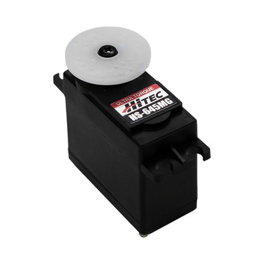
HS-645MG Servo-Clockwise (stock)-Stock Rotation
Welcome to ServoCity where you can get the parts you need to bring your ideas to life! From servos to switches, from actuators to Actobotics, we work hard to bring you the best components backed by unparalleled technical support
 www.servocity.com
Mrdchavez
New Member
Hello Moe i cant seem to get the gun to work. i copied that schematic you have for the servos. all this is new to me. I copied the code to the arduino from that instructibles tutorial. and nothing happens when i move the gyro? any ideas? everything seems to be getting power. the LEDS are all green. thx!This is what I use for all my wiring https://www.amazon.com/gp/product/B01LH1FR6M/ref=ppx_yo_dt_b_search_asin_title?ie=UTF8&th=1.
For Schematics, this is what I used for my canon:
View attachment 1649940
And this is what I used for sound:
View attachment 1649941
ksj
Well-Known Member
Follow this blog post from adafruit and see what your mileage is:Hello Moe i cant seem to get the gun to work. i copied that schematic you have for the servos. all this is new to me. I copied the code to the arduino from that instructibles tutorial. and nothing happens when i move the gyro? any ideas? everything seems to be getting power. the LEDS are all green. thx!

Arduino Lesson 14. Servo Motors
This is Lesson 14 in the Learn Arduino Adafruit series. In this lesson, you will learn how to control a servo motor using an Arduino. Firstly, you will get the servo to sweep back and forth automatically and then you will add a pot to control the position of the servo.
Mrdchavez
New Member
Hey where do you put that second servo? I know one goes into the gun itself there's some pictures but what about the second one? Thank you very much!The part looks like the right one. It is just a high torque standard size servo. The hs-645-mg has the best performance and cost factors out there.
I get all my stuff from servo city:
HS-645MG Servo-Clockwise (stock)-Stock Rotation
Welcome to ServoCity where you can get the parts you need to bring your ideas to life! From servos to switches, from actuators to Actobotics, we work hard to bring you the best components backed by unparalleled technical support
Mrdchavez
New Member
Excellent I got it to work! I just tried different pins for the pwm I'm not quite sure where they were labeled in the code but they actually work out! Thank you all!Follow this blog post from adafruit and see what your mileage is:
Arduino Lesson 14. Servo Motors
This is Lesson 14 in the Learn Arduino Adafruit series. In this lesson, you will learn how to control a servo motor using an Arduino. Firstly, you will get the servo to sweep back and forth automatically and then you will add a pot to control the position of the servo.learn.adafruit.com
Mrdchavez
New Member
So how did you actually wire in power in ground the two wires for the flashlight toggle and the two wires to turn on the cannon laser lights? Do you have some sort of schematic again I need all this. I did get the head tracker to work though! Additionally how did you actually put in the flashlight and connect it inside the gun? Do you have a picture of that exact setup? Thank you again!Oh, that's easy, just take a look here (Adafruit Audio FX Sound Board - WAV/OGG Trigger with 16MB Flash) to get an idea on how to wire the sound board. The buttons are your choice to which sounds you want them to make.
View attachment 1641920
They Discuss the Sound FX board in detail around the 13 minute mark Here:.
The rest of the wiring into the gauntlet is power in, Ground, 2 wires for flashlight toggle and 2 wires to turn on the cannon and laser lights.
ksj
Well-Known Member
Ground is common on everything. The mpu6050 is one of many gyroscopes out there now, so that is not the only option. Plus there are the qwiic/qt connections on some of the newer boards as a standard connector now.So how did you actually wire in power in ground the two wires for the flashlight toggle and the two wires to turn on the cannon laser lights? Do you have some sort of schematic again I need all this. I did get the head tracker to work though! Additionally how did you actually put in the flashlight and connect it inside the gun? Do you have a picture of that exact setup? Thank you again!
The light is basically wired in and inside the housing the wires are routed through a void to come out where a hole could be made or exists. Just be careful to not reverse polarity on connections as that is likely to burn up leds and lights.
For the leds/lights. Positive hooks to the pwm channel. negative hooks to common ground. I initially used 36" wires jumper wires. THen I switched over to jst-rcy 2 wire connectors.
For switches I used jst-xh and later made jst-ph to jst-rcy connector adapters.
The magic in wiring is figuring out in how to route it so it does not get bound and how to route it so it is not easily seen. Trial and error is your friend.
This was a wip video I did showing off my progress on my 800 some line python script using a wiimote for control:
Last edited:
Mrdchavez
New Member
That looks awesome but I'm really new to this and I don't really see how the flashlight is actually wired in? I see it looks like you took out the bulb and just stuck it in there and what looks like on moe's picture a double a battery in some sort of a holder. But how is the back of it actually activated? And connected to I suppose you Arduino or your wrist computer? Thank you again!
ksj
Well-Known Member
Well I have been putting off re-assembling things and doing another video ahead of doing a metal wrap around on the setup.That looks awesome but I'm really new to this and I don't really see how the flashlight is actually wired in? I see it looks like you took out the bulb and just stuck it in there and what looks like on moe's picture a double a battery in some sort of a holder. But how is the back of it actually activated? And connected to I suppose you Arduino or your wrist computer? Thank you again!
Similar threads
- Replies
- 4
- Views
- 252
- Replies
- 0
- Views
- 1,248
- Replies
- 17
- Views
- 1,882