You are using an out of date browser. It may not display this or other websites correctly.
You should upgrade or use an alternative browser.
You should upgrade or use an alternative browser.
Metro Exodus Hand Crank Charger
- Thread starter SpartaWorkshop
- Start date


Those look to be terminals similar to what you see on a speaker, but fully right angle. See images here.
Similar terminals are used on old high voltage devices, they are made by riveting a metal terminal to a paper or plastic backer. You can actually still by these as solderable terminal strips.
Similar terminals are used on old high voltage devices, they are made by riveting a metal terminal to a paper or plastic backer. You can actually still by these as solderable terminal strips.
Harrison4257
Active Member
 A quick mockup.
"Metro 2033" + "Metro: Last Light" are on the left.
"Metro: Exodus" is on the right (at least in the sketch 2 above this post).
I couldn't make out which one the game footage was, nor could I make out which of the 2 was pictured.
On the latter, conductive plates sit on top of the terminal lug, where it's crimped onto the copper wire. Where the former houses the copper wire. The wire was soldered onto the terminal lug in the latter(see pic).
Artyom, your a friend to dangerous tinkering.
Last edited:
Harrison4257
Active Member
Was thinking about the setup of the [all metal] Generator in Metro Exodus (and 2033 by chance).

This is a bad design. RIP Artyom. Unless that's why he taped up the hand grip.
This is a bad design. RIP Artyom. Unless that's why he taped up the hand grip.
The handle is just a handle. It has no electrical function. The motor wires are hidden behind the assembly, you can see three wires on the upper-left on the in-game images.
Here is how it should work:
Here is how it should work:
- Hand crank drives the generator, lets assume it is an alternating current generator, since there is a large diode and three wires exiting the motor.
- The coil shown may be a transformer. It would be used to increase the voltage level as the generator alone wouldn't actually create that much from hand cranking. A coil itself can actually hold a charge, but it collapses the second that power is no longer being applied.
- So a capacitor would be required to store the charge, unless you consider this device always wired to some external device with its own battery/capacitor. (Such as the headlamp)
Harrison4257
Active Member
This next post has been proven wrong, with many inconsistencies that are suspect.
"
1. This construct is all metal.
- Electricity travels through and arcs metal and metallic surfaces (and skin to a lesser degree).
2. There is a maximum current charge of 20 amps stored in that device.
- (Tested the volt capacitor, discharges way to fast to get anything useful.)
3. There are several bare electrical connections that touch the metal that can and will arc.
4. Artyom stores the charge if he's not using it.
- I've tested that for myself. So there is stored charge in the generator.
- youtube.com/watch?v=o-8lrZoHqUE for the second time I commented this. This is stored charge without any direct output.
- He charges with an AC Generator and stores it using a DC SuperCap (at least on my design) with heat loss in the diode/rectifier.
5. quora.com/What-is-the-maximum-voltage-a-human-can-withstand
- quora.com/How-does-a-human-body-conduct-an-electric-current
6. youtube.com/watch?v=NJRDclzi5Vg
- Within the 40 seconds he shorts the connection.
- Electroboom(from Canada) uses a 110v power connector (in Canada) and a high gauge drill.\
- 110v = 4.5A; answers.yahoo.com/question/index?qid=20071015184717AAC1raa
Form your own hypothesis and conclusion on what may occur.
I don't believe you've thought this through to the end concerning electrical charge before you commented.
It's all conjecture until someone builds and tests that out for themselves, at full charge. I'm not going to be that that person. I value my life.
"
"
1. This construct is all metal.
- Electricity travels through and arcs metal and metallic surfaces (and skin to a lesser degree).
2. There is a maximum current charge of 20 amps stored in that device.
- (Tested the volt capacitor, discharges way to fast to get anything useful.)
3. There are several bare electrical connections that touch the metal that can and will arc.
4. Artyom stores the charge if he's not using it.
- I've tested that for myself. So there is stored charge in the generator.
- youtube.com/watch?v=o-8lrZoHqUE for the second time I commented this. This is stored charge without any direct output.
- He charges with an AC Generator and stores it using a DC SuperCap (at least on my design) with heat loss in the diode/rectifier.
5. quora.com/What-is-the-maximum-voltage-a-human-can-withstand
- quora.com/How-does-a-human-body-conduct-an-electric-current
6. youtube.com/watch?v=NJRDclzi5Vg
- Within the 40 seconds he shorts the connection.
- Electroboom(from Canada) uses a 110v power connector (in Canada) and a high gauge drill.\
- 110v = 4.5A; answers.yahoo.com/question/index?qid=20071015184717AAC1raa
Form your own hypothesis and conclusion on what may occur.
I don't believe you've thought this through to the end concerning electrical charge before you commented.
It's all conjecture until someone builds and tests that out for themselves, at full charge. I'm not going to be that that person. I value my life.
"
Last edited:
I have thought this through very much so, with many years of electrical engineering school and work behind my comments.
I was trying to be helpful and educational. I am not trying you say your wrong, after all this is a mostly fictional device, and the artist may not have included all the parts needed for a proper generator.
1) If all the metal that holds things together is at the same electrical potential, then it won't hold a dangerous charge as there is not voltage difference, relative to the user holding it. Arcing can occur between the coil wire and enclosure, but unless the user holding the device is electrically connected between two points that have high voltage, then there is no actual current that travels though them. Artyom only gets hurt when he touches two contacts. This is also why you can touch a VanDeGraph generator with 10,000+ volts and not be hurt, as long as your not actually grounded. (Along with the fact that the generator has a tiny amperage capacity)
2) Amps on its own is not a measure of charge, it is a measure of current moving through a conductor. Amps are never driven from a storage device, it actually is pulled by the connected device and is a function of the resistance of the connected device. This is why volts is used for the potential amount of energy being produced.
Ampere-hour is used to measure charge in a battery, and is a function of how many amps it can provide for a certain amount of time before discharge. Total battery capacity is also affected by battery voltage. A capacitor's actual charge is measured in joules, and is a function of its capacitance (max charge), and voltage rating.
3) The main coil contacts look be be mounted onto paper insulators. A paper insulator is good up to several hundreds of volts.
4) In the video there are wires visible exiting to Artyom's body. So yes, he has some other charge holding device on him. There could also be a built-in capacitor next to the coil, behind the red and black terminals. We need to see the back of the game-model to be sure.
6) No trying to put down ElectroBOOM, but I wouldn't look to any YouTuber who makes dramatized videos for a education on electronics. His video isn't exactly inaccurate, but omits lots of actual details.
He, shorted a 110V A/C rail with a drill bit. So at the most that drill bit had 15 amps go through it before the fuse would have blown at the wall. So that is 1650 watts of power for a fraction of a second. A human can touch those same terminals, and get a shock about like you see Artyom get from the generator. (I have done it quite a few times on accident) The amount of amps a human would receive is far less due to resistance of skin.
Even if you built a generator of this size, the actual amount of total power output would be quite small. Even with the advantage of a geared driving mechanism. You can try this for yourself by getting one of those emergency flashlights that have a crank generator on the side. Even to power a small light takes a lot of human energy put into the system. The few seconds of cranking like Artyom does would only provide a few seconds if powering a non-LED light bulb as shown in game.
It is however very possible to build a functional prop however, with enough power to drive the on-board gauge and a more efficient LED to light up the gauge.
IsaacClarke345
New Member
Are you people still building this ? Created an account just to ask. This was easily the most interesting craft from Metro for me.
SpartaWorkshop
Member
I put most of my projects on hold due to the lack of time, but Im getting back to them very soon.Are you people still building this ? Created an account just to ask. This was easily the most interesting craft from Metro for me.
As for the charger, I decided that mine wont be functioning (i might make the voltmeter jump and retrofit an LED inside), and will be purely cosmetic. Shoot me a PM if you want the files to 3d print one.
SpartaWorkshop
Member
Its been too ******* long since this thread was updated! Im happy to say that my charger is 80% finished. Just have to sort out a few kinks...
Anyone know why my nema 17 wont generate past 5v?
Also I did a small update to my handle mechanism. Instead of the spring from pliers, Im using two springs from those hole punching tools you can find for a dollar.
Anyone know why my nema 17 wont generate past 5v?
Also I did a small update to my handle mechanism. Instead of the spring from pliers, Im using two springs from those hole punching tools you can find for a dollar.
Attachments
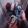
It is looking great so far. I think I spot some Lego bits in there.
The first thing to try is turning the screw on the front of your volt meter. It is there to allow calibration of the meter, but it probably wont turn far enough to compensate for the 5 volts.
The next thing to try is to take apart the existing meter you have now, and change the internal resistor. After all, a volt meter is just an amp meter with a fixed resistor added to make it work at a certain max voltage. Take a look at this analog panel meter clock for images of the resistor inside.
If it doesn't happen to have a resistor inside, then you will need to get a Amp meter instead. I searched eBay for "Analog Panel Meter Amps" and found some cheap models that look identical to your volt meter. You can always swap out the gauge face like the clock guy did above.
If you get an amp meter say rated for 10mA, it would take less power than a single LED light to actuate that meter. You then wire up a potentiometer in-line with the meter. This allows you to vary the resistance of the meter. Allowing you to calibrate the meter's maximum setting to match the maximum output your already getting from the generator. You may even end up with enough power left over to drive some LED lights.
Also, a Brushed DC motor should work better as a DC generator. Apparently, a NEMA 17 (Stepper) motor can be used as a generator, but needs a set of bridge rectifiers to use the full output of the motor.
Regarding the 5V output: Your hand crank has a fixed amount of hand power (Watts) that you adding to the system. Any gearing can't actually add any power to the system. It can only multiply/divide the rotations per minute, changing the low RPM of the input to a high RPM at the output. (The law of the conservation of energy.)
As an example: This brushed motor runs at 3500RPM, and consumes 3.2W @ 24VDC. (0.13 amps). To get 24V and 0.13A from this motor, you need to spin the input shaft at 3500RPM. However, if your pulling more than 0.13A from a connected circuit, then the voltage will drop.
SpartaWorkshop
Member
That explains a lot...
I dont remember if my voltmeter has a resistor or not. I did retrofit a led with its own resistor and I think that it eats up too much power.
As for the bridge rectifiers, I have two hooked up to each set of wires coming out of the nema 17 that are then hooked up to two 25v capacitors running in parallel.
Ill try to get a different motor and a smaller cog for it to see if it makes a difference.
And yes, I have two lego gears in there (like harisson has) due to the lack of alternatives.
Also thanks for the advice!!
EIt is looking great so far. I think I spot some Lego bits in there.
The first thing to try is turning the screw on the front of your volt meter. It is there to allow calibration of the meter, but it probably wont turn far enough to compensate for the 5 volts.
The next thing to try is to take apart the existing meter you have now, and change the internal resistor. After all, a volt meter is just an amp meter with a fixed resistor added to make it work at a certain max voltage. Take a look at this analog panel meter clock for images of the resistor inside.
If it doesn't happen to have a resistor inside, then you will need to get a Amp meter instead. I searched eBay for "Analog Panel Meter Amps" and found some cheap models that look identical to your volt meter. You can always swap out the gauge face like the clock guy did above.
If you get an amp meter say rated for 10mA, it would take less power than a single LED light to actuate that meter. You then wire up a potentiometer in-line with the meter. This allows you to vary the resistance of the meter. Allowing you to calibrate the meter's maximum setting to match the maximum output your already getting from the generator. You may even end up with enough power left over to drive some LED lights.
Also, a Brushed DC motor should work better as a DC generator. Apparently, a NEMA 17 (Stepper) motor can be used as a generator, but needs a set of bridge rectifiers to use the full output of the motor.
Regarding the 5V output: Your hand crank has a fixed amount of hand power (Watts) that you adding to the system. Any gearing can't actually add any power to the system. It can only multiply/divide the rotations per minute, changing the low RPM of the input to a high RPM at the output. (The law of the conservation of energy.)
As an example: This brushed motor runs at 3500RPM, and consumes 3.2W @ 24VDC. (0.13 amps). To get 24V and 0.13A from this motor, you need to spin the input shaft at 3500RPM. However, if your pulling more than 0.13A from a connected circuit, then the voltage will drop.
If you already have the bridge rectifiers in place, changing the motor or gear won't change the total amount of power you have available. This is limited by your own hand input. The resistor for the volt meter is probably internal, and you would need to take it apart to see if one is inside. Changing the resistor to a potentiometer (Variable resistor) allows you to calibrate the meter to match your available amount of power you already have.
LEDs have a fixed maximum amount of current they pull. Without a resistor, if you go past their fixed voltage drop, they will burn out. The resistor won't add any power draw, they just limit the amount of power the LED is allowed to use. A larger resistor can be used to lower the total current drawn, but the LED will be dimmer also. You can sometimes get more efficient LEDs that have more light output at the same current.
LEDs have a fixed maximum amount of current they pull. Without a resistor, if you go past their fixed voltage drop, they will burn out. The resistor won't add any power draw, they just limit the amount of power the LED is allowed to use. A larger resistor can be used to lower the total current drawn, but the LED will be dimmer also. You can sometimes get more efficient LEDs that have more light output at the same current.
SpartaWorkshop
Member
If this helps with anything, Im using this exact circuit:
When it comes to electronics I know the very basics. Im amazed I even managed to solder everything without burning myself.
I had to take the voltmeter apart because I had to paint it and I think it did have a resistor in place but im not 100% sure on that. Ill let you know tonight when I get home.
What can be done to make the mechanism more efficient? The rack and pinion system harisson designed works but it does need improvement, now how can it be improved? I have no bloody idea.
There is nothing wrong with that circuit. A stepper motor is just a motor with two AC coils. When used as a generator, it is like have two AC motors being spun by one shaft. As far as efficiency compared to a DC brushed motor: I can't say, that requires measuring and testing. All I do know is that a DC brushed motor is simpler in construction, and the rectifiers will drop the input voltage by about 1.2 Volts. However, I don't think efficiency is the issue, power draw is.
The rectifiers are needed to just convert the alternating current to DC current. In the video he only gets about 6 volts when the rectifiers are wired in parallel, but he gets about 15 volts when wired in series. This is exactly the same as when you wire two batteries in parallel, versus series.
In parallel you get twice the amount of potential current you can use, but less volts. In series you can get more volts, but less current. The total amount of actual power (watts) in both circuits is the actually same.
The biggest thing to focus on is total available power. Your generator has a fixed power of some sort. Efficiencies here won't make much difference, your not trying to get more miles out of an electric car.
In this case you have a 25V capacitor. The 25V is a measure of the maximum voltage it can handle without damaging the capacitor. The reason it is called a capacitor is that is a container that can store a certain capacity of potential energy. Capacity is measured in Farads or MicroFarads (uF). To use water as an analogy, imagine how a bucket can hold more water volume than a pint glass. Hence why physically larger capacitors hold more energy.
The voltage inside the capacitor will never go about the voltage of the generator. Instead the voltage in the capacitor will end up being an average of all the voltages over time that were driven by the generator. The stored energy inside the capacitor is a direct measure of that voltage, and the amount of amperage that has passed through the capacitor. However, just like a glass of water, it can only hold so much energy.
To use a water analogy again: Think of a capacitors like a local water tower. They are placed up high on a hill, so that any water stored inside can flow down via gravity. This is equivalent to voltage. The capacity of the water tower is fixed, by the volume of water inside. The amount of usable power in the tower is a measure of how much water is inside, and how high that water is above you. In electronics capacitors are actually used almost exactly how a city uses water towers. Capacitors provide instant local demanded power, and smooth out the voltage fluctuations. In your circuit they are smoothing out the voltage that the generator is putting out, as well as storing the energy it is making.
I assume you are trying to run an LED which most likely needs 20mA, and a volt meter. Lets assume this needs 10mA. So you need 30mA of current to run this circuit. (5V * 0.03A = 0.15Watts) That is a pretty small amount of power to generate.
The volt-meter you have is what 0-24V? Lets assume the volt-meter is made from a 10mA amp-meter, with a resistor added. (24V / 0.01A = 2400Ω). So the resistor inside is probably a 2400Ω resistor. (2.4kΩ). This also means it takes 0.24Watts of power to operate that meter at 24V. (24V * 0.01 = 0.24W)
You need the meter to instead react from 0 to 5V. (5V / 0.01A = 500Ω). So replacing the 2400Ω resistor with a 500Ω would make that amp meter work from 0-5V instead of 0-24V. The current required to move the amp-meter stays the same, but since voltage dropped, so did the amount of power required. (5V * 0.01A = 0.05Watts). By replacing that resistor, the meter is now four times as efficient. It's maximum voltage level has dropped, but amps are what count in your circuit.
SpartaWorkshop
Member
Hmm...
So I can at best squeeze out 5v with this thing?
(There go my dreams of running my pnv 57e goggles off of it lmao)
I had this crank radio thing you that had a rechargeable battery (one of those that look like three aaa batteries), would connecting it to the whole thing make it work more like the charger in game, or should I replace the resistor in the voltmeter ?
I am not saying 5V is the highest you can get, it is the voltage you said you are getting out now. I do know that no matter what you do to replace the motor, you won't get something that is 4x as efficient than you have now at converting human power into electrical power. Volts isn't the measure of power your achieving, Volts * Amps used is. Here is an example of a super simple generator using a DC motor and gears. The guy was able to get just over 1 watt of power from it, at just 1.5 volts
Changing the resistor on the Volt-Meter will make that meter work 4x as efficient if your input voltage is just 5V. (It also means it won't handle 24V anymore without damage). Changing it to an adjustable resistor makes it possible to calibrate it to the voltage to match what you get from the generator.
The crank radio thing is just a generator that is storing the energy into a battery. It only can store more energy because you crank for a longer period of time. The actual input power per second is still limited by how much effort a human can put into the system.
Church
Active Member
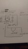
Ok so i know this was a while ago and im looking to make one as well and instead of using a fire extinguisher handle you could just use a caulk gun trigger and handle also depending on your motor and the amount of gears you have depends on the voltage and amps youll get but the easiest schematic is this.
Basically the motor gets its ac current filtered by diodes and it gets stored in your capacitor bank as dc current but super capacitors are desired as they act as batteries and can charge various devices such as phones or lights but as for powering fuze boxes itd have to be alot bigger than the small device you carry around
Basically the motor gets its ac current filtered by diodes and it gets stored in your capacitor bank as dc current but super capacitors are desired as they act as batteries and can charge various devices such as phones or lights but as for powering fuze boxes itd have to be alot bigger than the small device you carry around
Attachments
Hi, why you removed the model on thingiverse? :C Is possibile to get it somewhere else?Check out Thingiverse: Metro Generator by Harrison4257
Still uploading content of the Generator.
The handcrank is always an issue.
Similar threads
- Replies
- 7
- Views
- 950
- Replies
- 14
- Views
- 13,203
- Replies
- 1
- Views
- 1,400
- Replies
- 8
- Views
- 15,653