No offense taken. You files are your own to control.
I opened your assembly. (I only needed the v38 step file). It looks good so far. I am guessing a lot of it is temporary items you will improve as you go.
But here are some tips, please do as you want though. Learning CAD takes time.
- The pipe on the left side could use rounded corners. This can be done using a sweep operation.
- The gear profiles need to be meshed properly, it looks like you already have done this on the above animated post. GearGenerator.com is what i used for my Pip-Boy gears.
- The gears don't have to be quite so thick. 10 or 6mm will work just as well.
- Look to McMaster or GrabCAD for CAD models of real hardware, that way your screws and nuts will be accurate to what you can use to actually put it together. You can even 3D print the models to make lightweight versions of items that don't need to be metal.
- Your sheet metal parts have zero radius on the inside corners. Real sheet metal always has some amount of inside radius. Typically half the material thickness. Fusion 360 may even have a sheet metal mode that will help guide those features to look more real. Also, even if your are 3D printing the metal parts, an inside bend radius greatly strengthens the joint.
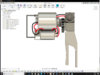
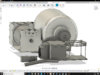
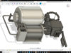
- Looking at this image as reference, it looks like some of the parts are intended on being welded instead of bent sheet metal.
A work in progress that file is.
Again, since I will bend - or weld in this case- half of the machine in metal, The holding bracket I might use a Steel bar in fact. I didn't find it necessary for me to put more work into something that I'll just throw away in the future. (updated)
The through holes and fasteners will be marked out with the generator of your own choosing. That particular set is the L shaped bracket in the back that bumps up against the Generator, and they vary in size.
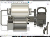
As for the picture in reference, I used some aspects. of the design as reference If I welded the pipes to the actual generator, it may warp its curvature and cease its function. So I opted for my own particular design.
*Update*
Redesigned the Handle, the attachment points are 3 1 at the base to the power bank, 1 from the screw cap to the electrode plates, and 1 from the handle to the electrode plates. If you aren't sure it will hold up, just weld the thing.
I've only used sweep maybe twice before, with little success. Thanks for the tip!
*Update x 2*
Believe I've messed up the first Step file. I inadvertently double posted two 60 tooth gear pieces on top of one another. Here's a corrected version in the .zip file.
You may notice that the Cap bank has altered some, I've tinkered with it, trying to fit the Super Caps inside. There is far to little room to mess around.
The [new] capacitor bank is untested and in the process of being printed out and tested (Super Cap 2.5V 120F if you please) , yet I've included that as well. >.>
*Update x 3*
Added in the Escapements for the wires on both ends. They may be a little to large.
Added the L bracket instead of the straight bar. I'll round the corners later if need be. *Falls down dead.*