February 17, 2024

Any addict knows you always need a little more to get that feeling you got from your first high and I've discovered the same is true with scratch building and kit bashing studio scale models.*
Fresh off the big high from my 232 Imperial Probe Pod, my next build will be the TIE Bomber. This one seems to have had a heyday 10 years ago but I haven't seen many that weren't 3D prints lately.
I already had a good start on the kits needed so I started collecting kits and materials until I got to the point where I got to the point where I could start. That time is now. Some parts I'm going to cast in resin due the cost of the kit so as not to go completely bankrupt. I got lucky last weekend at a model swap meet when I picked up an original Hawker Harrier and Stuka kit for $80 for both.

That brings me to WHERE to start?

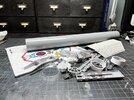
I'm not using a starter kit and I'm still sorting out what form the armature will take so I figure I can start with one of the many subassemblies. I chose the wings.
It was brought to my attention a detail that some people miss is that the wings aren't matching so you need two Vader TIE kits. On the outside of the center panel there's a detail strip that is on the top on the left wing and on the bottom of the right one. If you use the two wings included in the kit that strip will either be on the top or bottom of both sides depending on the orientation of the wings. So you need two kits. Who knows if this was intentional or just by accident when the the original was being built.


With that straightened out I started on the wing extensions and figuring out the measurements. I've read of people doing their wing extensions in varying widths:
12.6mm
15mm
15.8mm
I know there are some templates out there and I'm capable of making my own but I found it faster to cut some strips out of card stock and just taping on the wings to see what looks best. Afterwards I would then just trace the pieces onto another piece of card to make the final template. I know it seems like a lot of work it's just a quicker way of working for me.


I started with the 15mm measurement and it didn't quite look right so I tried 1/2". Again, not looking right. Too small.

In the end I found myself in that familiar place we've all been in where I was getting tired and nothing looked right.

I'd be curious to hear from anyone out there what measurements for the wings you used.
Any addict knows you always need a little more to get that feeling you got from your first high and I've discovered the same is true with scratch building and kit bashing studio scale models.*
Fresh off the big high from my 232 Imperial Probe Pod, my next build will be the TIE Bomber. This one seems to have had a heyday 10 years ago but I haven't seen many that weren't 3D prints lately.
I already had a good start on the kits needed so I started collecting kits and materials until I got to the point where I got to the point where I could start. That time is now. Some parts I'm going to cast in resin due the cost of the kit so as not to go completely bankrupt. I got lucky last weekend at a model swap meet when I picked up an original Hawker Harrier and Stuka kit for $80 for both.
That brings me to WHERE to start?
I'm not using a starter kit and I'm still sorting out what form the armature will take so I figure I can start with one of the many subassemblies. I chose the wings.
It was brought to my attention a detail that some people miss is that the wings aren't matching so you need two Vader TIE kits. On the outside of the center panel there's a detail strip that is on the top on the left wing and on the bottom of the right one. If you use the two wings included in the kit that strip will either be on the top or bottom of both sides depending on the orientation of the wings. So you need two kits. Who knows if this was intentional or just by accident when the the original was being built.
With that straightened out I started on the wing extensions and figuring out the measurements. I've read of people doing their wing extensions in varying widths:
12.6mm
15mm
15.8mm
I know there are some templates out there and I'm capable of making my own but I found it faster to cut some strips out of card stock and just taping on the wings to see what looks best. Afterwards I would then just trace the pieces onto another piece of card to make the final template. I know it seems like a lot of work it's just a quicker way of working for me.
I started with the 15mm measurement and it didn't quite look right so I tried 1/2". Again, not looking right. Too small.
In the end I found myself in that familiar place we've all been in where I was getting tired and nothing looked right.
I'd be curious to hear from anyone out there what measurements for the wings you used.
Attachments
Last edited:


