Hi all!
Some of you might have seen my last thread with a review of a cryocan, and I expressed that my frustrations with it made me want to make my own— well, here's my progress on that! Once I'm done, I'm going to try and get this machined in aluminum, but I'll also be sharing the files publicly through this thread for anyone to use.
Also, anybody know if the cryocan is still at the Universal Citywalk in LA? I just moved here and actually seeing the piece in person would be so helpful, but I'm not exactly sure where in the Citywalk I'd need to go and don't want to waste the parking money if its not—but I need to see about how many indents that bottom piece has (I have 22 right now and it looks right, but might be 24? My math might have been off).
All these measurements were made with the assumptions that the diameter inside the can is 65mm and the centrifuge vials are the same size, as those are what I used to make the measurement scale
Here's the measurements made in Photoshop, I used screenshots, the photos taken of the prop while on display, and I started using photos from the Chronicle collectibles promotional photos, but I actually think there are a few things incorrect about the model, so I switched back to only reference from the actual prop:

I see now that a few of the measurements aren't there or are a little off, I made a lot of the measurements on the spot while I was modeling in blender and forgot to write it down, and a lot of the measurements were made for my own reference/notes, so if anything is confusing or if you have questions please let me know!
IMAGES
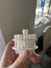
Here's the progress with the 3D model (yes, I forgot the notch, but I will be re-doing it anyways for reasons stated bellow):


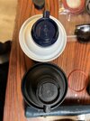
TEST PRINT
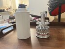
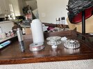
I then 3d printed the parts to test if the middle disks would properly screw together, if it would fit inside a barbasol can and if the centrifuge tubes fit. Once I get the bolts and o-ring in the mail, I'll be testing the threaded holes as well as the if the o-ring/o-ring indent is the right size.

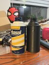
1) Does it screw together: despite a faulty STL/print, yes!

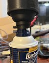
2) Does it fit in the barbasol can: Yes! Snuggly.

3) Do the centrifuge tubes fit in the rings? NO. I made the rookie mistake of making it snug to the diameter of the flat part of the tube.

And a side note, I need to make the bottom lip a bit taller

I have some re-modeling to do to fix some of these issues.
MECHANISM
So I want to reinvent the wheel I guess... With the inner tube I'm doing the same sort of channel that I've seen other models use, but I noticed in a lot of screen shots that the cryocan does not have this vent here:

at least not in the spot I see on a lot of the other replicas, if its there at all.

I can't find that vent in a single screenshot, but maybe I'm not looking hard enough. Without actually seeing the prop myself, its hard for me to figure out if it's just always facing away from the camera—so I could definitely be wrong, but might as well try and make a prop without that channel.
SO I came up with this...

...but only after I attached the bottom tube to the bottom disk and it was 2am so I didn't even think about how there would be no way to fit that tube into the base with the disk on top of it. In v2 I'll be fixing that by making that bottom tube a separate piece that screws on (too many parts? Maybe.)
PROBLEMS to be fixed in V2:
Any advice, critique, and observations would be welcome! Thank you!
Some of you might have seen my last thread with a review of a cryocan, and I expressed that my frustrations with it made me want to make my own— well, here's my progress on that! Once I'm done, I'm going to try and get this machined in aluminum, but I'll also be sharing the files publicly through this thread for anyone to use.
Also, anybody know if the cryocan is still at the Universal Citywalk in LA? I just moved here and actually seeing the piece in person would be so helpful, but I'm not exactly sure where in the Citywalk I'd need to go and don't want to waste the parking money if its not—but I need to see about how many indents that bottom piece has (I have 22 right now and it looks right, but might be 24? My math might have been off).
All these measurements were made with the assumptions that the diameter inside the can is 65mm and the centrifuge vials are the same size, as those are what I used to make the measurement scale
Here's the measurements made in Photoshop, I used screenshots, the photos taken of the prop while on display, and I started using photos from the Chronicle collectibles promotional photos, but I actually think there are a few things incorrect about the model, so I switched back to only reference from the actual prop:
I see now that a few of the measurements aren't there or are a little off, I made a lot of the measurements on the spot while I was modeling in blender and forgot to write it down, and a lot of the measurements were made for my own reference/notes, so if anything is confusing or if you have questions please let me know!
IMAGES
Here's the progress with the 3D model (yes, I forgot the notch, but I will be re-doing it anyways for reasons stated bellow):
TEST PRINT
I then 3d printed the parts to test if the middle disks would properly screw together, if it would fit inside a barbasol can and if the centrifuge tubes fit. Once I get the bolts and o-ring in the mail, I'll be testing the threaded holes as well as the if the o-ring/o-ring indent is the right size.
1) Does it screw together: despite a faulty STL/print, yes!
2) Does it fit in the barbasol can: Yes! Snuggly.
3) Do the centrifuge tubes fit in the rings? NO. I made the rookie mistake of making it snug to the diameter of the flat part of the tube.
And a side note, I need to make the bottom lip a bit taller
I have some re-modeling to do to fix some of these issues.
MECHANISM
So I want to reinvent the wheel I guess... With the inner tube I'm doing the same sort of channel that I've seen other models use, but I noticed in a lot of screen shots that the cryocan does not have this vent here:
at least not in the spot I see on a lot of the other replicas, if its there at all.
I can't find that vent in a single screenshot, but maybe I'm not looking hard enough. Without actually seeing the prop myself, its hard for me to figure out if it's just always facing away from the camera—so I could definitely be wrong, but might as well try and make a prop without that channel.
SO I came up with this...
...but only after I attached the bottom tube to the bottom disk and it was 2am so I didn't even think about how there would be no way to fit that tube into the base with the disk on top of it.
In v2 I'll be fixing that by making that bottom tube a separate piece that screws on (too many parts? Maybe.)PROBLEMS to be fixed in V2:
- Resize centrifuge holes (bottom disk holes might be smaller than top disk??)
- Add notch to center tube
- Fix threading between disks
- Make tube under the bottom disk threaded and separate
- Recount/recalculate indents on upper base
Any advice, critique, and observations would be welcome! Thank you!
.gif")