You are using an out of date browser. It may not display this or other websites correctly.
You should upgrade or use an alternative browser.
You should upgrade or use an alternative browser.
Iron man motorised faceplate electronics tutorial!!!
- Thread starter 7sinzz
- Start date
7sinzz
Well-Known Member
problem I see... is people taking this FREE info (where we have done all the work).. and FREE CODE.. and then go to offer kits or things THEY profit from..
Please tell me this isn't happening!!!!
That SUCKS!!!!
gbmaster137
New Member
This code is working ok. Its hard to say, your problem can be (i think):
1. damaged servo (or wrong degrees setup)
2. Broken button (or wrong button install)
3. Mistake in your montage. have take a look one more time. Good luck!
p.s. by the way - first button push - it must leds blink and ON. so - you have no leds, but code doesnt know it.")
Just checked, everything is ok, but im still having the same problem
Sent from my HTC One X+ using Tapatalk 2
Just checked, everything is ok, but im still having the same problem
Sent from my HTC One X+ using Tapatalk 2
Hm... you know, only way i see:
1. take another servo - check it.
2. take your servo and check it with servo-tester.
3. take another arduino and check wirh your servo.
this code is realy work, i tried it on 3 different helmets. (one more time Thanks to 7sinzz for post)
xl97
Master Member
do you have any arms or load on the servos?
what servos are they? more so.. what are they rated for? are you powering them enough/correctly?
some are 4.8-6.0+ voltage...
and the current they use under load can be over 1 amp spikes..
still sounds like the GNDS arent all tied together though..
what servos are they? more so.. what are they rated for? are you powering them enough/correctly?
some are 4.8-6.0+ voltage...
and the current they use under load can be over 1 amp spikes..
still sounds like the GNDS arent all tied together though..
dentingleopard
New Member
you could probably use 1 LM7805 regulator..
the problem MIGHT be (again Im as new as everyone else here)
depending on the LOAD we're only guessing at the real current needs/draw from the servos..
thinking..
batery to +5v regulator..
going to/through a transistor before going to the LEDS will have a small/slight voltage drop.. (probably under 0.7)
so calculate the resistor value used for the leds based off +5v - trans drop value..
here is a my quick wiring diagram from the other day:
make note of:
1.) this is for MY code
2.) double, triple check the transistor you use and get the pinout correct
3.) calculate resistor values based on the actual parts/battery..etc used IN THE PROJECT
http://dmstudios.net/misc/IM_eyeCircuit/IronMan_circuitLayout_xl97.jpg
as memebr says.. the Arduino (in this case) is nothing more than a smart button.... it POWERS/DRIVES nothings..
if you look at the IM led eye circuits boards I made.. you will see the leds, resistors and transistor are all one board/piece..
there are some solder pads on it, for the battery +/- pack.. but also a pad for the Arduino control/signal line..
the only real contact/connection with the Arduino..
i have a question for xl97 i will be useing your diagram what type of regulator and npn transistor would i need and the only thing ill be changeing is the red led for green
gbmaster137
New Member
do you have any arms or load on the servos?
what servos are they? more so.. what are they rated for? are you powering them enough/correctly?
some are 4.8-6.0+ voltage...
and the current they use under load can be over 1 amp spikes..
still sounds like the GNDS arent all tied together though..
They are rated for 4.8~6.0V, use angle is =<160°, the power comes from the usb cable connected to the computer, and tested it both with and without the plastic arms they bring.
Just tested with the LED connected and still had the same problem, and the LED didn't turn on, then, i used the code with the flikering LED and got some progress, LED goes on and of when its supposed to go but now the servos do the open/close motion then nothing, something like this
1st button push: LED flikers and turns on
2nd button push: LED turns of and servos do the open-then-close motion
3rd button push: LED flikers and turns on, servos do nothing
4th button push: what happens in the 2nd push
5th button push: what happens in the 3rd push
This then happens in that sequence(2nd, 3rd, 4th, 5th)
Sent from my HTC One X+ using Tapatalk 2
xl97
Master Member
the regulator is a LM7805 (I think it says that? really small on the pic?)
the transistors "I" used were posted.. BC1725's or something off the top of my head.. (I can check though if you like)
calculate the resistors to match the fV of the leds you choose..
(reds were just the image.. i used whites & blues in my tests.. all haeing vF of around 3.1-3.2)
the transistors "I" used were posted.. BC1725's or something off the top of my head.. (I can check though if you like)
calculate the resistors to match the fV of the leds you choose..
(reds were just the image.. i used whites & blues in my tests.. all haeing vF of around 3.1-3.2)
xl97
Master Member
is this the same USB powering Arduino? or this just some sort of USB power cable thing?
try following the diagrams...
and using an external battery source..
NONE of what is done her should be using USB for anything.. (except to upload your sketch to the Arduino)
what are your leds specs?
your not the one using the odd led string.. or 9-12v pre-wired leds are you?
* for everyone posting for help..
try to give al ink or brief summary of your projects.. with so many people pasting with questions..
"I" cant keep whos got what, wired up how straight any more.
Everything is ok, the servos works, also the lights with a little adjust, now i am going to make a PCB to make this circuit as compact as possible. For now i will install the cervos on my WM MK II helmet. Wish me luck
Good luck:thumbsup
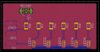
Hello again. I'm beginning to design the PCB with Eagle and I wanted to be sure that everything's in place so I took a screenshot.
I still have to work on it though but I won't make drastic change with components and routes...
Doest it look like it's ok? I'll have to check for a manufacturer now and the requirements. If you have any ideas.
I still have to work on it though but I won't make drastic change with components and routes...
Doest it look like it's ok? I'll have to check for a manufacturer now and the requirements. If you have any ideas.
Attachments
xl97
Master Member
circuit wise.. looks fine... looks like the PCB board file I posted a while back for the eye pcb's..
however..
1.) have you tested 5 SMD leds? bright enough for you? what size leds? 1206's?
2.) pcb size? looks to be rather big to fit IM bucket behind the eyes..
I like and use iTead/iMall alot..
i will be trying SEEED studios for the first time now..
and have heard decent things about Elecrow as well..
for good quality boards..but more in price.. you can also check out OSHpark <-- US based though I believe..
The LEDs are 1206 indeed. I found some smd led 380-550 mcd. Have you some suggestions about brightness? I still have superbright 5mm standard LEDs I can use, just a small change in the PCB. But it's only 20-25° angle, so would give more problem to diffuse the light to avoid spotted eyes ^^
The board size is 50mm x 25mm but as I said, I still have work to do on it so I'll put the components closer to each others to downsize the board.
Concerning my board, I've a doubt concerning connection between resistors and transistor and "ground" in general:
- in schematics I linked all the resistors together and linked those to the transistor
- name of the "link" is GND
- I linked the transistor to a solder pad named GND
- Link between transistor and solder pad is also named GND
- I made 1 polygon named GND on the top layer and 1 polygon named GND on the bottom layer.
So on the board schematics it seems nothing's really connected between solder pad, transistor and resistor but I know the whole board is considered as GND and thus, everything's connected. Just wanted to be sure I didn't screwed anything.
I join the schematics:

Again, thank you for your patience answering to my noobish questions
gbmaster137
New Member
This different code will make the LED flicker then fade on, one second after the faceplate closes. Mimicking a powering up function. Demonstration here. Thank you to guitarkizta for this code:
#include <Servo.h>
//servo 1
Servo myservo;
Servo myservo1;
int val; // variable for reading the pin status
int val2; // variable for reading the delayed/debounced status
int buttonState;
int pos = 0;
int pos1 = 180;
int servostatus = 0;
int switchPin =2; // Switch connected to digital pin 2
int ledPin = 5;
int ledPin2 = 18;
void setup() // run once, when the sketch starts
{
//servo 1
myservo.attach(9);
myservo1.attach(10);
pinMode(switchPin, INPUT);
pinMode(ledPin, OUTPUT);
buttonState = digitalRead(switchPin);
myservo.write(0);
myservo1.write(175);
pinMode(ledPin2, OUTPUT);
}
void loop() // run over and over again
//servo 1
{
val = digitalRead(switchPin); // read input value and store it in val
delay(10); // 10 milliseconds is a good amount of time
val2 = digitalRead(switchPin); // read the input again to check for bounces
if (val == val2) { // make sure we got 2 consistant readings!
if (val != buttonState) { // the button state has changed!
if (val == LOW) { // check if the button is pressed
if (servostatus == 0) { // is the light off?
servostatus = 1; // turn light on!
myservo.write(0);
myservo1.write(180);
delay(1000);
digitalWrite(ledPin, HIGH);
delay(50);
digitalWrite(ledPin, LOW);
delay(00);
digitalWrite(ledPin, HIGH);
delay(50);
digitalWrite(ledPin, LOW);
delay(00);
// fading
for(int fadeValue = 0 ; fadeValue <= 255; fadeValue +=5) {
// sets the value (range from 0 to 255):
analogWrite(ledPin, fadeValue);
delay(30);
}
} else {
servostatus = 0; // turn light off!
digitalWrite(ledPin, LOW);
delay(15);
digitalWrite(ledPin2, LOW);
myservo.write(180);
myservo1.write(0);
}
}
}
buttonState = val; // save the new state in our variable
}
}
I'm using this code and everything is correctly wired up and looks almost like in the video, and the power source is the same as in the video (same USB used to upload the code to the arduino).
Tested without changing anything in the code, then tested by changing the degrees to 1 and 150, and with both i had the same problem stated in my previous post
Piotr Minor
New Member
Hello there!
That's my very first post here on therpf. While waitng for my servos (orderd on dx.com) I was playing with my new toy - the Arduino UNO. I've read all pages of this topic and I'm impressed of what you guys did here. But let's back to the Arduino - I've altered the code of 7sinzz just to see the "flicker thingy" for LEDs and gone a little further.
Sorry for the crapy quality (something gone wrong with the audio). I will upload some more when I'll get the servo motors and finish the helmet.
Hello to all of you once more!
Last edited by a moderator:
made007
Sr Member
Please tell me this isn't happening!!!!
That SUCKS!!!!
Well if its happening... Mods should chime in..... And this thread should be pinned so that everybody can see it. And that way people doing what xl97 said wont take advantage of other members...
But hopefully they wont do this... I hope
Hey I would like to know if this servo would be enough to lift the face plate and maybe do the jaw as well? My face plate will be resin, fiber glass and bondo. There will be two of these lifting the face plate.
Hitec HS-85MG+ Premium Metal Gear Micro Servo - Canada Robotix - Toronto, Ontario
Hitec HS-85MG+ Premium Metal Gear Micro Servo - Canada Robotix - Toronto, Ontario
Last edited:
dentingleopard
New Member
HEY WAS WONDERING IF YOU COULD HELP ME OUT WITH A SIMPLE PROJECT IM TRYING TO DO A SIMPLE ARDUINO PROJECT. I WANT TO TURN ON AND OFF SOME LEDs MY IRON MAN ARC REACTOR AND BOTH REPULSORS AND MAYBE SOME IN THE FEET LOL via ARDUINO BUT WHAT I WANT IT TO DO IS WHEN I TURN IT ON I WANT IT TO DO A POWERING UP TYPE FX WHEN TURNED AND HAVE JARVIS SPEAK SAYING HELLO OR SOMTHING AND WHEN I TURN IT OFF ITS FADES AWAY LIKE POWERING OF AND JARVIS SAYING GODD BYE SIR OR SOMTHING . IF U CAN HELP OR KNOW SOME ONE WHO CAN IT WOULD BE APRECIATED THANKS
- - - Updated - - -
AND IF CAN BE DONE ALL BY A WIRELESS REMOTE
- - - Updated - - -
AND IF CAN BE DONE ALL BY A WIRELESS REMOTE
xl97
Master Member
1.) for any sort of audio.. your Arduino board will need some 'add-ons'.. like a Waveshield or MP3 shield/break out board or something..
2.) you'll have to figure out how many leds in each place you want to control.. Arduino only has so many I/O pinsyou can use.. and (usually) each one can only drive 1-2 leds (max 40mA output per pin,,,200mA total pins).. so you'll have to look into getting around that.. either by using an external chip like a shift register or transistor type set-up/approach perhaps...
3.) for it fade in/out you'll need PWM.. and the Arduino has a limited number of them.. (if you end up using an Adafruit Waeshield.. it also uses some of your I/O pins and a few PWM pins as well I believe)
4.) repulsors, Arc reactor to feet... thats a fairly big area.. and wires running up/down the suit..all connected to 1 main Arduino..
Similar threads
- Replies
- 1
- Views
- 317
- Replies
- 1
- Views
- 469
- Replies
- 2
- Views
- 559