borgknight
New Member
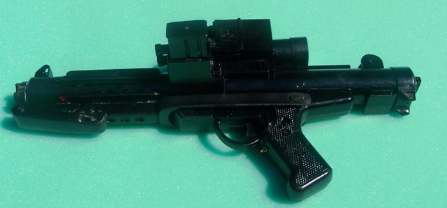
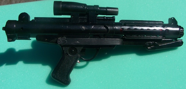
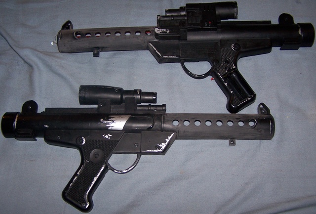
A while ago, I started modifying my Hasbro E-11. I opened it up, added a laser sight, chopped the front piece off, and replaced the LED in front.
I did not take pics of those steps, however.
I did take pics of the next steps:
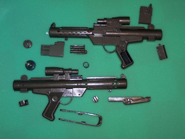
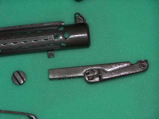
I cut off the "fins" that were at the wrong angle:
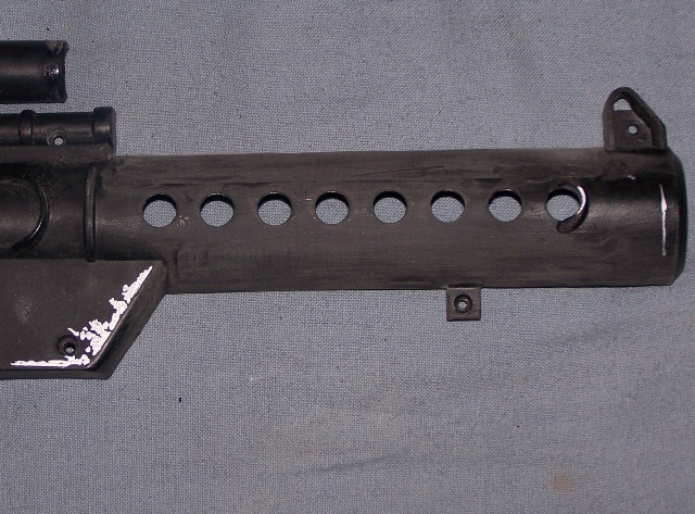
Then I cut off the front curved "fins," marked where the new holes needed to be drilled, and made small pilot holes with a Dremel:
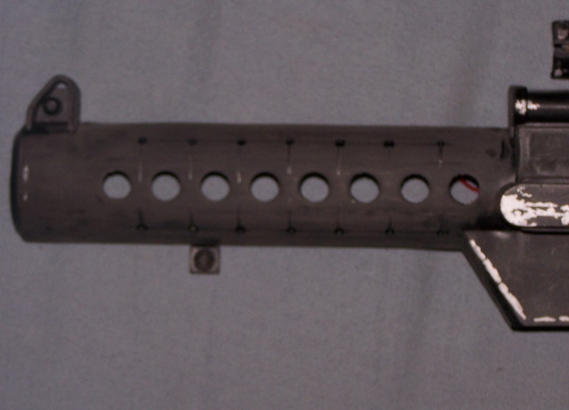
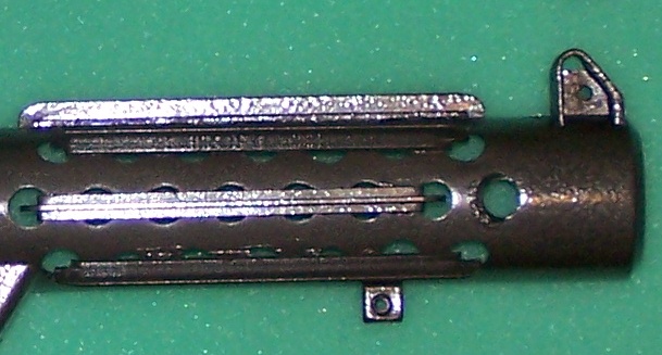
Drilled and trimmed the new holes:
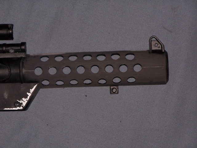
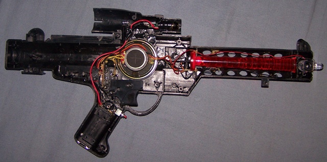
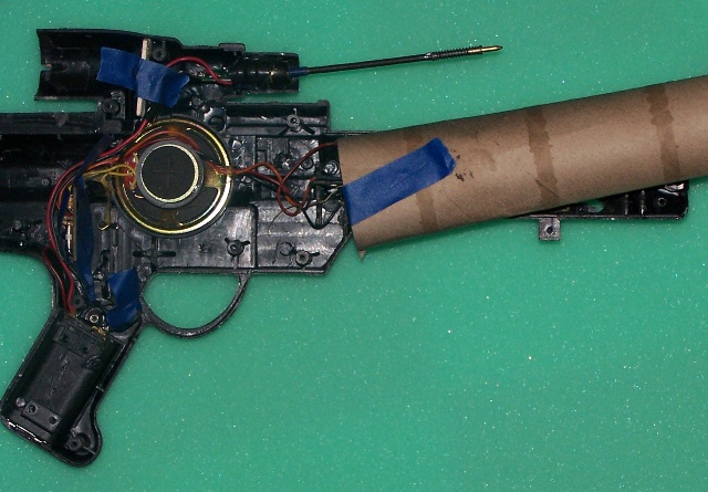
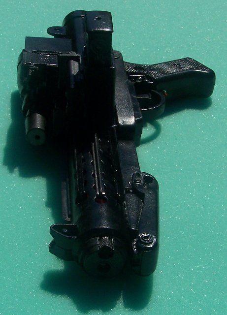
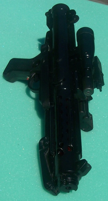
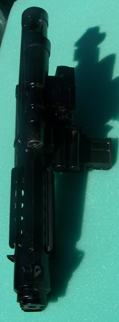
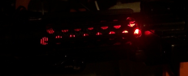
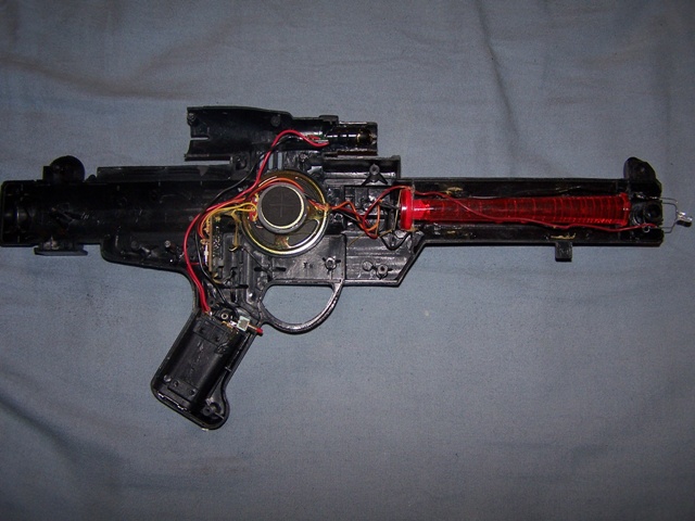
Here is the internal view of the blaster:
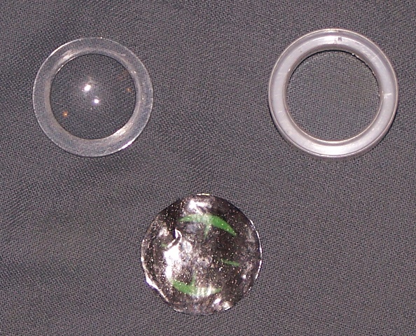
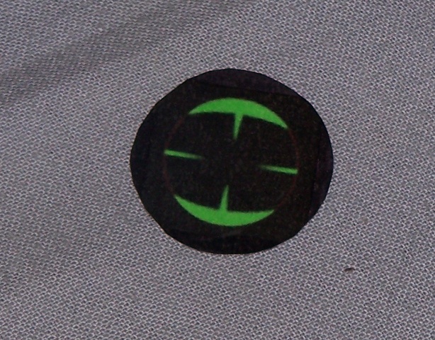
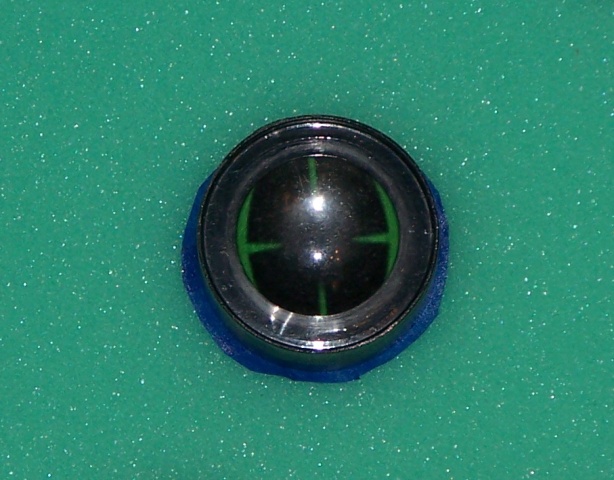
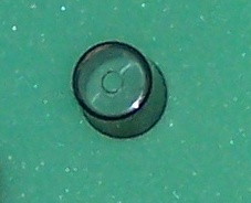
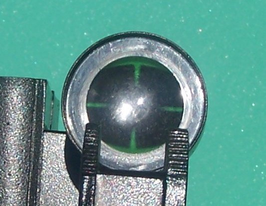
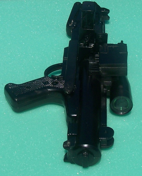
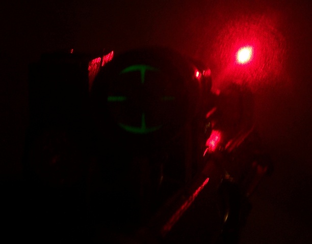
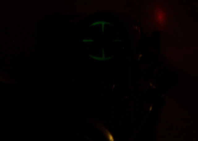
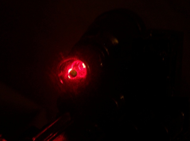
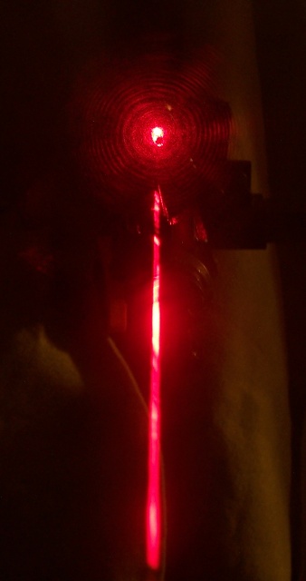
This is the element from a laser pointer glued into the scope:
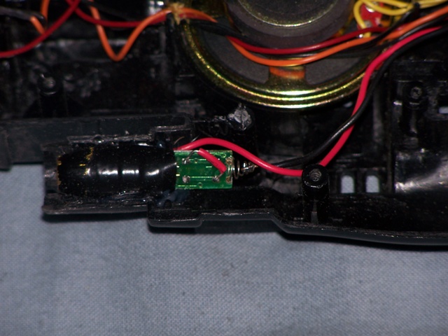
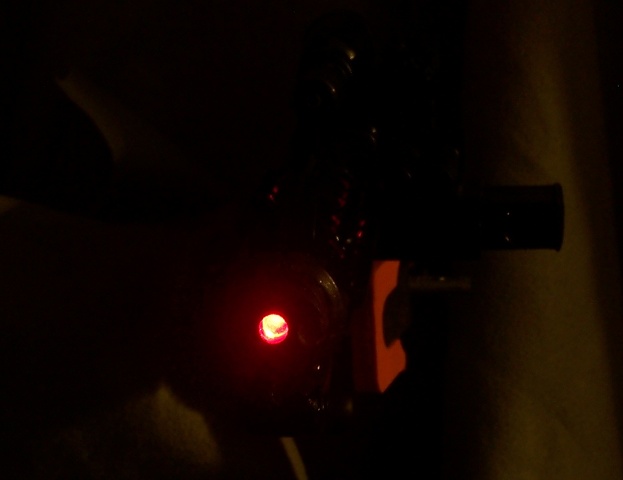
I attached leads to the existing battery contacts to avoid adding a second power supply. Here is the switch:
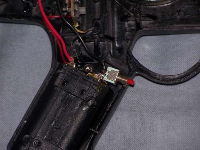
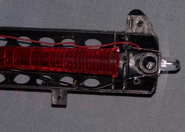
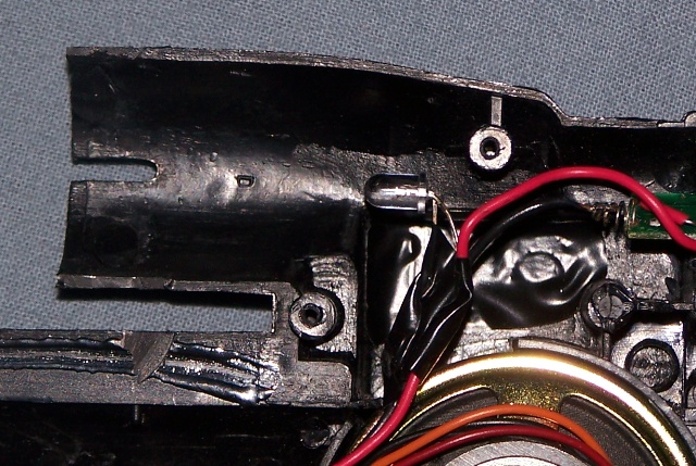
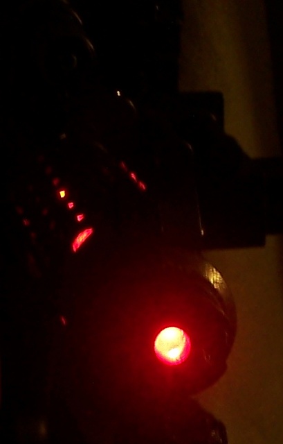
This is a focus on the wiring I added:
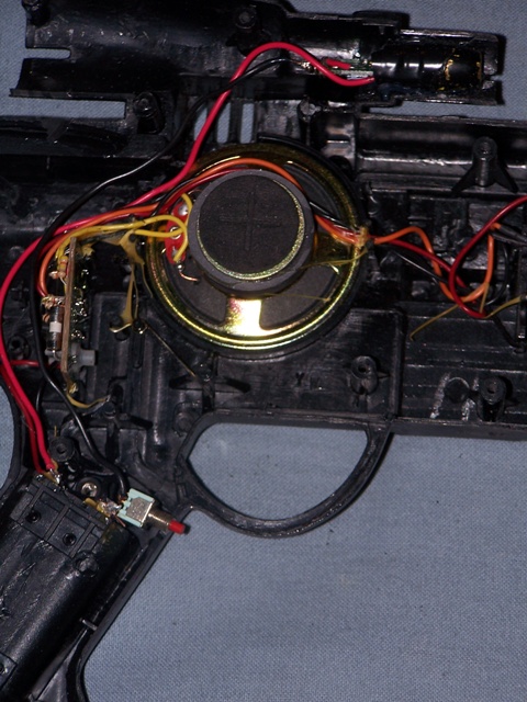
The red wire goes from the positive battery contact to the positive contact on the laser. The black wire goes from the negative battery contact to the switch, and from the other contact on the switch to the negative contact on the laser.
More pics as the project progresses.
I did not take pics of those steps, however.
I did take pics of the next steps:
I cut off the "fins" that were at the wrong angle:
Then I cut off the front curved "fins," marked where the new holes needed to be drilled, and made small pilot holes with a Dremel:
Drilled and trimmed the new holes:
Here is the internal view of the blaster:
This is the element from a laser pointer glued into the scope:
I attached leads to the existing battery contacts to avoid adding a second power supply. Here is the switch:
This is a focus on the wiring I added:
The red wire goes from the positive battery contact to the positive contact on the laser. The black wire goes from the negative battery contact to the switch, and from the other contact on the switch to the negative contact on the laser.
More pics as the project progresses.