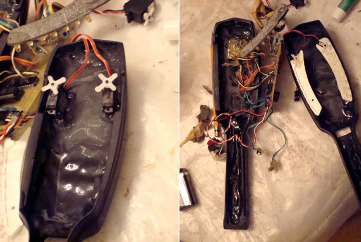
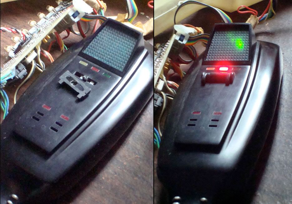
My current project is a PKE meter, so I thought I'd share with the RPF. I'm also keeping track of it on my website here: The PKE Meter Project – Canceled
I'm a slow builder, so I hope you'll bear with me as I go along.
11/16/08: Getting Started
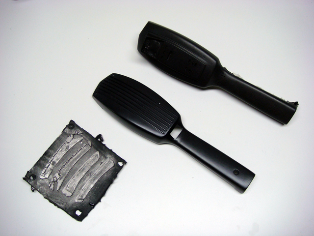
The goal of this project is to construct a replica of the PKE meter as seen in the Ghostbusters films. The original prop was built from an Iona shoe polisher. While these polishers are no longer made, you can usually find them online and in pretty good condition. However, a significant amount of modifications need to be done to convert the polisher into a PKE meter. I was lucky enough to find a great fiberglass kit with the majority of the modifications already completed. As you can see, the kit consists of two primary pieces; the front face and the rear face. It also includes four pieces which are to be used to construct the wings. This will be my first time working with fiberglass, so it should be interesting.
11/23/08: Electronics
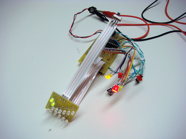
The PKE meter wouldn't be much without a good set of electronics. I picked these up from the resident expert in custom prop electronics, Hyperdyne Labs. These electronics are especially nice because they include a dual-mode display screen. Research has shown that there were multiple versions of the prop used as the PKE meter. These versions differed in that the sequencing LEDs in the main display were oriented in different directions. One version had the LEDs sequencing top-left to bottom-right, while the other version went from bottom-left to top-right. The display board for these electronics can sequence in either direction as dictated by a simple input switch. The electronics kit also features:
11/28/08: Dremel gives you wings!
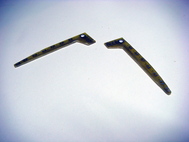
I figured I'd tackle the electronics portion first since they'll need to be fitted into the kit. The electronics come up with a single printed wire board that can be separated into two boards used to connect the LEDs that will go in the wings of the PKE. Using a cutting wheel and my trusty Dremel, I separated the two wing boards. I then used the grinding wheel to smooth all the edges. Be very careful not to hit any of the traces while cutting or grinding, otherwise you run the risk of breaking the electrical connection, which could prevent the LEDs from getting power later on. In the event you do cut any of the traces (as I did), you can solder a spare piece of wire down to bridge the gap in the trace. Afterwards, I rinsed the boards off with some water to remove any particulates which could prevent the solder from properly adhering to the boards when I attach the LEDs, which will be my next step...
01/30/09: More electronics work
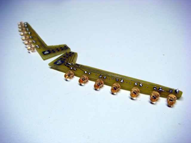
Here you can see the LEDs have been attached to the wings. I soldered them on and cleaned up the boards with some isopropyl alcohol to remove any residual flux from the solder. I was going to wire up the ribbon cables to attach the wings to the main circuit board, but I figured I should wait until I have all the components in place in the body kit so I'll know how long to cut the wires.
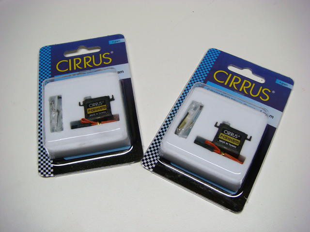
I also picked up two micro-servos, which will be used to move the wings up and down. I went with the Cirrus CS-101 micro-servo, which I purchased from The Hobby People. The wiring harness for these servos is slightly different than that of those called out in the instruction manual for the electronics, so I'll need to figure out which wire is which...
Lastly, I gave the body components a bath is some warm soapy water to remove any residual contaminents from the molding process.

I'm a slow builder, so I hope you'll bear with me as I go along.
11/16/08: Getting Started
The goal of this project is to construct a replica of the PKE meter as seen in the Ghostbusters films. The original prop was built from an Iona shoe polisher. While these polishers are no longer made, you can usually find them online and in pretty good condition. However, a significant amount of modifications need to be done to convert the polisher into a PKE meter. I was lucky enough to find a great fiberglass kit with the majority of the modifications already completed. As you can see, the kit consists of two primary pieces; the front face and the rear face. It also includes four pieces which are to be used to construct the wings. This will be my first time working with fiberglass, so it should be interesting.
11/23/08: Electronics
The PKE meter wouldn't be much without a good set of electronics. I picked these up from the resident expert in custom prop electronics, Hyperdyne Labs. These electronics are especially nice because they include a dual-mode display screen. Research has shown that there were multiple versions of the prop used as the PKE meter. These versions differed in that the sequencing LEDs in the main display were oriented in different directions. One version had the LEDs sequencing top-left to bottom-right, while the other version went from bottom-left to top-right. The display board for these electronics can sequence in either direction as dictated by a simple input switch. The electronics kit also features:
- dual-mode display screen with sequencing LEDs
- variable frequency sound effects that increase/decrease with wing position
- driver circuit for wing LEDs with adjustable frequency
- servo driver circuit to move wings up and down
11/28/08: Dremel gives you wings!
I figured I'd tackle the electronics portion first since they'll need to be fitted into the kit. The electronics come up with a single printed wire board that can be separated into two boards used to connect the LEDs that will go in the wings of the PKE. Using a cutting wheel and my trusty Dremel, I separated the two wing boards. I then used the grinding wheel to smooth all the edges. Be very careful not to hit any of the traces while cutting or grinding, otherwise you run the risk of breaking the electrical connection, which could prevent the LEDs from getting power later on. In the event you do cut any of the traces (as I did), you can solder a spare piece of wire down to bridge the gap in the trace. Afterwards, I rinsed the boards off with some water to remove any particulates which could prevent the solder from properly adhering to the boards when I attach the LEDs, which will be my next step...
01/30/09: More electronics work
Here you can see the LEDs have been attached to the wings. I soldered them on and cleaned up the boards with some isopropyl alcohol to remove any residual flux from the solder. I was going to wire up the ribbon cables to attach the wings to the main circuit board, but I figured I should wait until I have all the components in place in the body kit so I'll know how long to cut the wires.
I also picked up two micro-servos, which will be used to move the wings up and down. I went with the Cirrus CS-101 micro-servo, which I purchased from The Hobby People. The wiring harness for these servos is slightly different than that of those called out in the instruction manual for the electronics, so I'll need to figure out which wire is which...
Lastly, I gave the body components a bath is some warm soapy water to remove any residual contaminents from the molding process.
Last edited:


