DeAgostini MF Internal bracing issue...

Jun Austria

Well-Known Member
One fine day, I was doing some work on my Falcon. Then my 4 pound cat decided to jump on it.
The falcon at that time was supported on a 4 pcs M6 bolts. And this what happened...

InkedWP_20180906_22_54_02_Pro_LI.jpg

The 2 bolts at the rear end of the model somehow was bent inwards. This is due to the force from the top.

I'm planning to display my model on a flight mode. And I'm planning to use those 4 bolt connector to support the model internally.
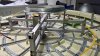
So with a lack of structural integrity. I have to do something about this. And this is what I came up.

InkedWhatsApp Image 2018-09-08 at 10.51.47 AM_LI.jpg

Using small square metal tubing and some bolts and screws. I managed to transfer all the load towards the 25mm x 25mm vertical center support.
The metal tubing will be fixed first by bolts. Then the bolt supporting the upper hull can be adjusted to the top hull inner height by adjusting the nuts until the bolt touches the upper hull.

WhatsApp Image 2018-09-08 at 10.51.49 AM.jpeg

And heres the upper view. I still need to lower the horizontal tubing by 20mm. Coz I decided the put back the gunner bay on top.
And I'm ok not including the internal detail. Coz I don't see myself looking into that. I just want to see the whole ship like a studio model.

Just sharing.

Cheers
 

Attachments

  • WhatsApp Image 2018-09-08 at 10.51.47 AM.jpeg
    WhatsApp Image 2018-09-08 at 10.51.47 AM.jpeg
    122.6 KB · Views: 518
The Falcon framework is made of tin. If your cat bent part of it just thread in an M6 bolt and bend it back. Failing that, you can always just order a replacement frame section. I applaud your ingenuity here but I think this is rather excessive for what you gain. I have mine wall mounted with none of this and it seems just fine. Now if you can come up with a way to reinforce the mandibles, I'll be all over it.
 
The Falcon framework is made of tin. If your cat bent part of it just thread in an M6 bolt and bend it back. Failing that, you can always just order a replacement frame section. I applaud your ingenuity here but I think this is rather excessive for what you gain. I have mine wall mounted with none of this and it seems just fine. Now if you can come up with a way to reinforce the mandibles, I'll be all over it.

I didn't bothered to replace the bottom frame coz its not that obvious anyway. But one of the frame on the top hull it is badly bent so I bought the replacement. Also one of the vertical support at the rear engine broke off from the screws. I just use epoxy to put it back. Coz that part is no longer available in my region.

As for the mandibles, I'm on it. Just need to solder the frame together before fixing it inside the mandbiles. Basically using the spare tubing I got from the ikea lamp. I formed a U shape support to keep the 2 mandibles at the same level. Will post the pics one its done.
 
As promised. I'm showing how I reinforced the mandibles...

WhatsApp Image 2018-09-17 at 7.49.59 AM.jpeg
Using the left over square tubing from the IKEA lamp. I fashioned a "U" shape support that is fix on the middle frame. All fixing were done by nuts & bolts.
The support will insure even level for both mandibles.

WhatsApp Image 2018-09-17 at 7.49.56 AM.jpeg

WhatsApp Image 2018-09-17 at 7.49.58 AM.jpeg
I'm still contemplating on tying back the frame towards the center support. Coz without the top, the whole mandible will still sag.
This due to the lower hull frame being flexible without the top hull.
 
Very cool internal framework addition you have made. I got rid of mandible sag by using rivets to permanently attach the mandibles. SInce I magnetized the sidewalls I can still separate the upper and lower hulls.

I have a question and you seem to be in a position to know the answer!

My top and bottom hulls no longer sit the proper distance apart so the docking rings pegs no longer line up.

What's the correct distance between the bottoms of the two turret rings?
 
Last edited:
Cool concept and execution for strengthening the internal structure . How do you plan to attach the mandibles to the support beam/ rods though ?


:cheersGed
 
Very cool internal framework addition you have made. I got rid of mandible sag by using rivets to permanently attach the mandibles. SInce I magnetized the sidewalls I can still separate the upper and lower hulls.

I have a question and you seem to be in a position to know the answer!

My top and bottom hulls no longer sit the proper distance apart so the docking rings pegs no longer line up.

What's the correct distance between the bottoms of the two turret rings?

Hi. Like you, I also use magnets to make my panels removable...


This is for the purpose of unforeseen repair.

As for your top hull. The model kit top hull is not properly supported in my opinion. The top curve frame is relying on the side frame and the side frame is relying on the bottom hull frame. But the top and bottom frame still show a bit of flex. And that bit of flex can make some parts mis-aligned.

This can be seen when you try to fix the 2 docking ring and triangular side panels. You have to slightly lift the top hull to put the docking ring in place. Seeing this, I supported the top hull with some bolts transferring the weight to my center pole. Relieving the side and bottom frame from the weight of the top hull. I will get back you on the distance you are requesting when I get home.

Hi qedmac66. I'm still contemplating on the tie back. But I'm leaning towards a telescoping brass tubing that I can lock in place. :)
 
Last edited by a moderator:
If I would rebuild a Deago MF.......

I would put some sort of Epoxy/Resin inside the floor and top before joining to permanently affix the panels to the structure. I also went the micro magnet route on the side panels as I didnt want to permanently join the halves for future ease of adding additional lighting or board replacement.

Nice. But too messy for me. I just use Loctite as a threadlocker for all the screws just to prevent them from loosening.
 
Question for the group; is there a space between the top of the main hold walls and the hull after installation? Or is it a tight fit?
 
I think I can start closing her up....

IMG-20181015-WA0001.jpgIMG-20181015-WA0004.jpgIMG-20181015-WA0003.jpgIMG-20181015-WA0002.jpg

I think it's easier to paint the main color when she is on a vertical position.

IMG-20181015-WA0000.jpg

Thanks to this. I managed to finish my metal support.
Just need to learn how to weld metal next time.
 
This thread is more than 5 years old.

Your message may be considered spam for the following reasons:

  1. This thread hasn't been active in some time. A new post in this thread might not contribute constructively to this discussion after so long.
If you wish to reply despite these issues, check the box below before replying.
Be aware that malicious compliance may result in more severe penalties.
Back
Top