Customised Hasbro ETA-2 Actis

JimmyB

Member
So the thinking was Jawas found a crashed ETA-2 Actis in the sand dunes of Tatooine and sold it to everyone's favourite mechanic in Mos Eisley's Hangar 3-5, to be butchered and upgraded to hyperspace-capable by Peli Motto's long suffering pit droids.

Here's the basic design, done in Blender using a fortuitous 3D scan of the Hasbro toy which can be found on Thingiverse. The blue box poking out at the bottom will be a battery box made to look guts-on-the-outside (more on that later... hopefully).

Jedi_ETA2_Actis_21_for_presentation.png


From the 3D model I figured out how to scale the UV maps of the meshes for printing on A4 paper as cutting plans, which are then stuck to styrene sheet using 3M spray adhesive. Here's a sample layout to show you what I mean.

Jedi_ETA2_Actis_21_UV_example.png


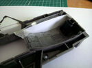
Then it was time to start hacking away at the Hasbro Actis. Here are the casualties.

ETA2_model_build 021.JPG


And here are the beginnings of a beautiful experience (despite the cuts and expletives the neighbours probably heard). Yes, that's a cheap toothbrush from Boots converted into a battery powered oscillating sander with removable velcro sanding discs cut from sheet sandpaper.

ETA2_model_build 007.JPG


I didn't want a droid sticking out of the wing for this, so I hacked out and filled the hole, and then made another hole for a custom greeble that'll be sticking out of the wing :confused:

The solar panels were also a write off when the Jawas found it, so I hacked away at them to create holes that match the toy's holes in the main part of the wing. That was fun (sarcasm).

ETA2_model_build 015.JPG


More to come later.
 
It's been a long time since I did any kitbashing, so my old box of kit spares was lost to home moves sometime in the last couple of decades. Details were made for the underside pit wells and former droid pit from recycled computer spares, copper wire, styrene and plastruct beams.

ETA2_model_build 020.JPG


DSC_0027.JPG


ETA2_model_build 014.JPG
 
Test fitting the extended tail. Styrene was cut to shape from the 3D design, and then thermoformed using boiled water from the kettle in a glass that was roughly the right diameter. Once the styrene softened and took the shape it was placed in a glass of very cold water to set the shape (video demonstration of the technique by Dave's Model Workshop). This is the 1mm thick inner hull for the tail that will have some strength to it, and an outer layer of 0.5mm styrene will serve as panelling that will extend further than the boundaries of the inner to give a better scale thickness to the edges. I'll refine the shape with more waterforming and cross section pieces.

DSC_0028.JPG
 
Your skills at scratch building/transforming that model are still tops(y)...as for the swearing, I'm sure:lol::lol:. I'm lucky to live in a detached home where my closest neighbors are far away from me (just in case the yelling/swearing would go out of hand!)
Eager to see your next update on that interesting project!

Thanks for the encouragement, Jo :). This is the project I'll be applying aluminium tape to.

The underside of the wing tips were cavities with raised detail so needed to be filled. Supports were added to the inner edges and within the cavity, base layers of 1mm styrene cut to shape and inserted, topped with scored and snapped 0.5mm. To the right are some of the tools I found useful for tidying panel edges: rifflers, an engraving point in a pen handle, a dart (very tough and sharp), triangular file and an engineer's scriber.

DSC_0030.JPG


The rear wing undersides were also open so needed to be filled using the same methods. I followed the small panel lines at the trailing edge to make a continuous run and consolidate the additional styrene panels.

ETA2_model_build 017.JPG
 
The next step will be a scratchbuilt cockpit which will entail lighting. I used a small profile gauge to get the shape for where the side panels will sit.

DSC_0033.JPG


DSC_0034.JPG


That gave me a template.

DSC_0036.JPG


The final model will have cockpit lights, headlights on the underside where the holes for the missile shooters were, and engine lights. I wanted to keep it as simple as possible. A local poundshop has had cheap LED string/fairy lights powered by two AA batteries with 20 LEDs on the string, for £1. The wiring between them is extremely thin single strand copper wire that seems to be insulated with a clear enamel coating. The poundshop also has £1 LED aluminium torches (flashlights) that use 9 LEDs that are too bright to look at directly, powered by 3 AAA batteries, which is what the scratchbuilt engines will be built around. After taking a torch apart it has a simple toggle switch, and the aluminium casing acts as the negative connector to the LEDs which means I can cut off the end containing the LEDs to save weight and, as it turns out, the torch LEDs will still run very brightly off the string light AA battery pack (the central LED is missing in the photo below as, at £1 a pop, I thought I'd check out one of the bulbs).

DSC_0052.JPG


I see no reason why I won't be able to run two engine torches, two sets of cockpit string lights, and a couple of LEDs from a different type of string lights for the headlights (the bulbs have excellent shaping that looks just like a headlight when switched on), all from the single AA battery pack that will be mounted in the tail. It isn't as if I'll have the lights switched on for hours on end, although I did test the string lights last year for an anniversary party's decorations and they were going strong after being switched on for more than 8 hours, and were barely even warm to the touch. The string can be cut to length with a pair of scissors, and it's fairly straightforward to sand a cut wire down to make a new connection. I should be able to mix and match cool white and warm white LEDs on the same string in series for a blend of 1970s tungsten look if wanted.

Cockpit panel lights were a puzzle as I don't want to use fibre optics. It transpires that the tiny string LEDs (I know the package says large but they're very small as far as I'm concerned) can be shaped as the tiny LED itself sits in a transparent plastic bubble. After carefully filing a bubble down I got it shaped to less than 1.5mm square, the bonus being it stands proud of the proxy panel it sits in and doesn't have the problems of viewing angle parallax occluding and shifting the light when it sits below the panel for backlighting; it looks like a lit button mounted on top of the panel. This approach should work for the larger cockpit lights, anyway, and on the cheap, although I'll have to be careful handling them once filed down.

Untouched bubble at the top, and filed bulb between that and the ruler and set into a few pieces of beer can aluminium sheet.

DSC_0048.JPG


DSC_0050.JPG


Transparent glass paint also works great for colouring the LEDs (Pebeo Vitrail was tested). Scrap that; the paint eventually peeled away.

And that's it for now. Thanks for reading my longwinded rambling.
 

Attachments

  • DSC_0035.JPG
    DSC_0035.JPG
    1.8 MB · Views: 10
Last edited:

Your message may be considered spam for the following reasons:

If you wish to reply despite these issues, check the box below before replying.
Be aware that malicious compliance may result in more severe penalties.
Back
Top