Building a manageable A-wing

3d-builder

Sr Member
This is the smallest model I ever made parts for so far,
the goal is to make it smaller but still look very similar
to the SS A-wing.

I found the old toy up in the attic that was released in the 90's,
I still had it in the box, and decided it was a real nice scale and a very
decent toy. I liked the shape of the hull and thought the shape of the engines
were perfect.Other things were kind of toy'ish but that's why it's a toy!:lol It also turns out to be just about 2x's bigger than the old snap kit released in the 80's of the A-wing.

Most of the parts were made from styrene and clay for vacuum forming.
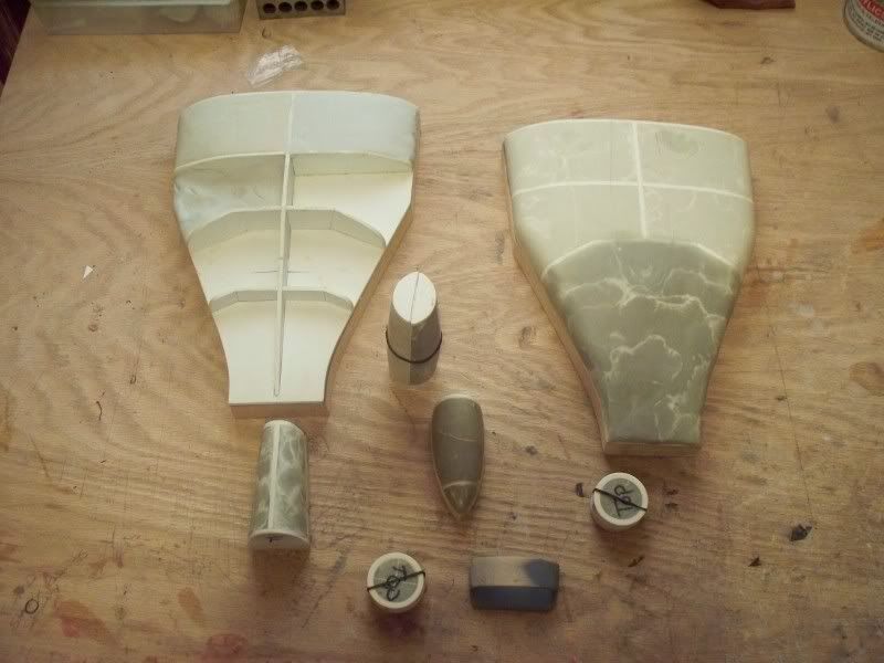
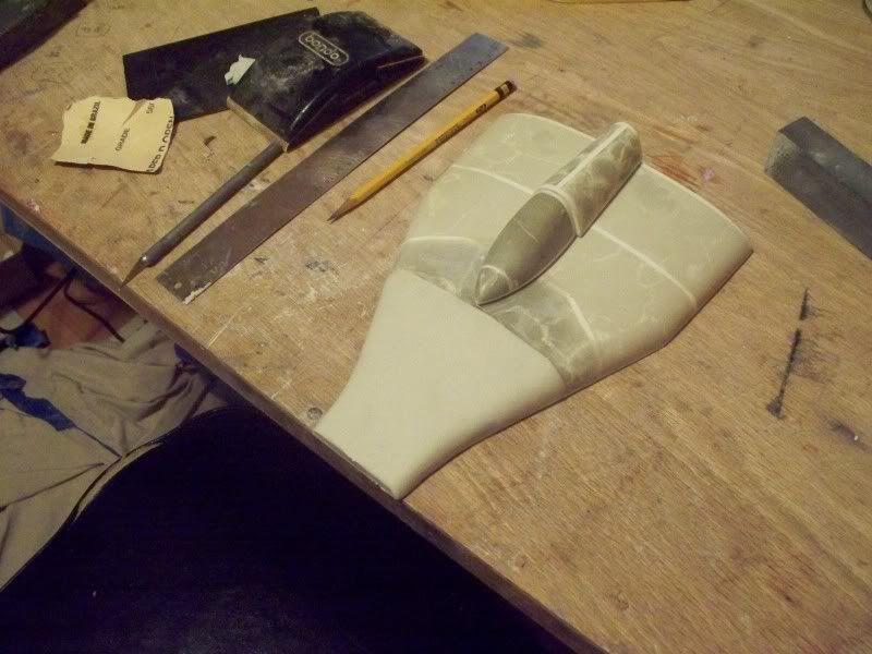
100_3322.jpg
 
Last edited:
If you look ahead in the thread you see i had already
started this and deleted pics to start over.:lol:thumbsdown
 
Last edited:
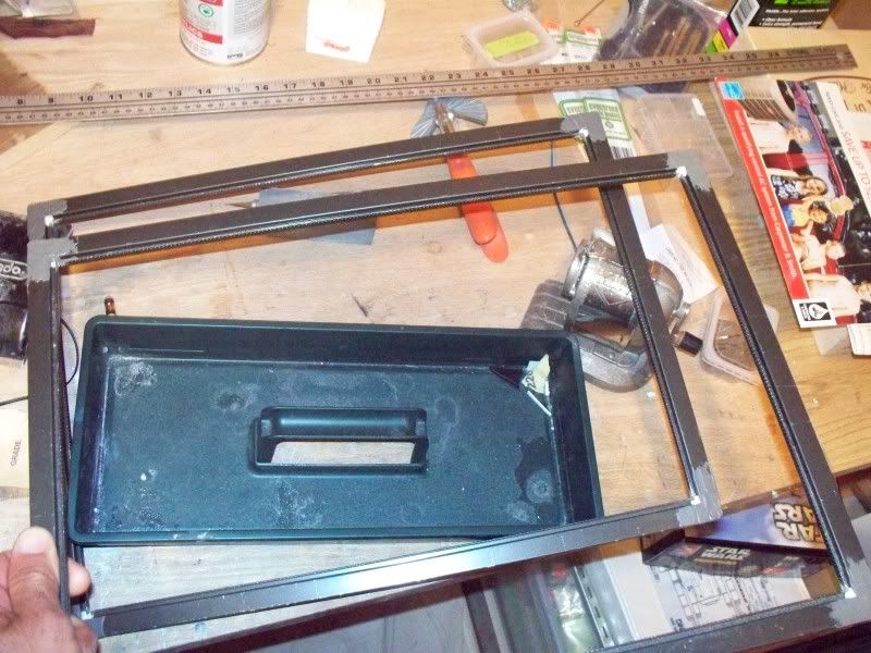
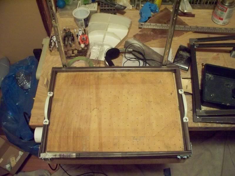
I really needed a upgrade for the former i was using
for this project. The origial frame work that held the
plastic in the oven, was made of aluminum window
screen frame. It has these removeable plastic 90's
for the corners, thats part of the problem! When you
have to heat the thicker styrene 2mm and up it's in
the oven for a good clip.By the time its ready to come
out of the oven those plastic 90 deg corners in the frame
work begin to melt yieeeks!:angry:thumbsdown
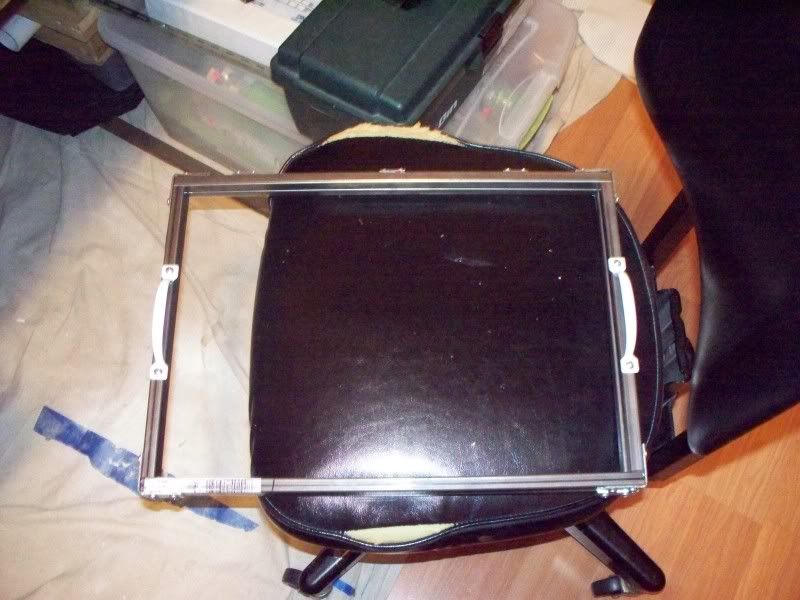
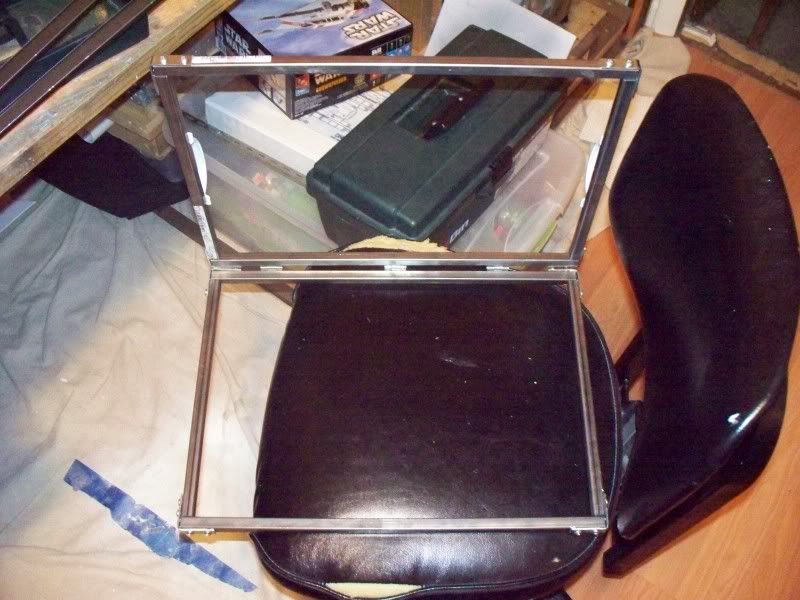
So i went down to Home Depot and picked up
some square stock steal.....(wanted aluminum but
didnt have the correct size), hinges, handles, L-brackets.
And i came up with this rough tough mudder!

Original stuff......
100_3327.jpg


New frame work........
100_3328.jpg

100_3329.jpg

100_3330.jpg
 
Last edited:
After the risers are removed from the formed patterns and the flash
this creates removed. There is still an extra 3mm that needs
to be sanded away from each part.This is because all of the parts are
built up on 3mm styrene bottom profiles.
So masking tape is cut at 3mm wide and wrapped around the parts,
then it is marked with pencil and sanded until the extra 3mm is removed.
100_1937.jpg

100_1940.jpg

100_1941.jpg
 
The A-wing is a cool fighter, to realize the shape you have to cut away
most of the model if you build it this way. So first I tape both hulls together
and find the middle of both and run the lines, as you can see in the pics.
Dimensions taken off the toy.The dremel tool does the heavy work almost up to the line, then hand sanding for the rest.In these pictures I cut away the shoulder areas on the top and bottom hulls.
100_1944.jpg

100_1946.jpg

100_1947.jpg
 
The gun wells are drawn out and then dremeled away also,
same goes for the center insert sections, and the missile launch tubes.
100_1949.jpg

100_1952.jpg

100_1954.jpg

100_1962.jpg

100_1963.jpg

100_1964.jpg
 
After the launch tubes are cut out on each side, I chose
to fill them with some evergreen strip channel.The channel
pushed it back just far enough to give it a real nice channeled
look in this scale and it bent perfectly to shape.After this was done on each side, two reinforcement bulkheads were cut out and added. These add needed strength to the side of the hulls were it is hollow.
100_1972.jpg

100_1973.jpg

100_1974.jpg
 
With just about all being cut away minus the tub opening,
it's time to start filling back in the center sections.These
need to be cut out because the sit a little lower in their
travel down the top and bottom hulls.So some poster board to make a
template.That template is then traced onto some 2mm styrene and cut out,
it ended up being exactly 2x's bigger than the old snap kit, as you can see
in the pics as I marked it off twice.
100_1977.jpg

100_1986.jpg

100_1987.jpg
 
Now for some panel lines these were drawn on by pencil and scribed
on the center section before it was fitted.Since the discovery of the
center section being 2x's bigger than the old snap kit, I chose to scale
up all the panel lines and mark their placement using this kit.
100_1994.jpg

100_1999.jpg

100_2003.jpg

100_2027.jpg

100_2019.jpg
 
Last edited:
You have seen some pictures of the canopy nose cone and rail
that are bit out of order.this is how I created it, it was just
dremeled away after it was marked out.That particular plug was created
just for 90 percent of it to be dremeled away. Because the cone would be nearly impossible to create attached to the rail I made it this way. You can see
in the pic the left over piece in the background.
100_1950.jpg
 
Next I glued down the canopy rail and nose cone. Once the rail and cone were glued down I took the dremel tool and dremeled away the inside shape
created by the rail and cone piece. Next I placed A piece of styrene from
the underside and traced the shape on it. This would aid in capturing the profile
of the tub at the very top, this will be later built up on and turned into a pattern for the tub, so it could also be vacuum formed.
100_2049.jpg

100_2051.jpg

100_2056.jpg

100_2058.jpg

100_2060.jpg

100_2062.jpg

100_2076.jpg

100_2078.jpg

100_2080.jpg

100_2081.jpg
 
With the tub part vacuum formed I added a little shelf
to add some details on. Still a lot more to do in the cockpit
but you get the idea how it was made...thats what is most
important!
100_2084.jpg

100_2083.jpg

100_2087.jpg

100_2088.jpg

100_2089.jpg

100_2096.jpg
 
Ok here is a part I though I was going to be able to form
but the drop and gravity is against me. So I hollowed it out
and decided to cast it in resin. I sent it off to modman06 and he
cast it for me.You can see the hollowed part next to the solid one
originally made.These are the F-16 like intakes that sit between the engies
on the A-wing at the rear.Big shout out to Al thanks man! Here are the parts Al cast for me
couldn't get photobucket to uplaod for me yesterday!
100_2075-1.jpg

awingmold009.jpg

awingmold011.jpg

awingmold013.jpg

awingmold014.jpg
 
Last edited:
Next up making the inner bulkhead the engines attach to.
I jut held the oak tag up to the profile of the shoulder cut outs,
and kind of just winged the rest making templates until I got it right.On
the inside of the model I glued down some evergreen strip to mark the location
and recess of this bulkhead. Then I went ahead and added the gun well
bulkheads, and backed them up with right triangles to give it strength.This area
will need to be drilled while in place for the laser cannons.
100_1979.jpg

100_2071.jpg

100_2066.jpg

100_2073.jpg
 
With the bulkhead sorted out for the most part,
it was time to start the placement of the engines and stabilizers,
first the panel lines were drawn and scribed.The lower engines
stabilizer was glued to it's engine. The top stabilizer and lower
sit at a angle, to keep the proper angle at the top I mad a little
angle type of jig to lean it up against while gluing.Then a hole is drilled in the engines front fascia.The the engine is slipped into place, I then rotate the lower engine until it's stabilizer matches the angle as the top. When this is achieved I tape a ruler to both to lock them in place.With the ruler taped to the stabilizers, I take a pencil and mark through the pre-drilled hole in the engine fascia, placing it's location on the inner bulkhead. This mark is then drilled out so a bolt and wing nut can hold the engine to the bulkhead.This allows for easy mounting and removal of the engine right up until final fitting
when it will already be painted.Thats about where I am right now I have a ton more pics but just to speed things up a bit!
100_2104.jpg

100_2105.jpg

100_2106.jpg

100_2110.jpg

100_2111.jpg

100_2113.jpg

100_2114.jpg

100_2116.jpg

100_2117.jpg

100_2118.jpg

100_2121.jpg

100_2124.jpg
 
Back
Top