bttf time display

who45

Well-Known Member
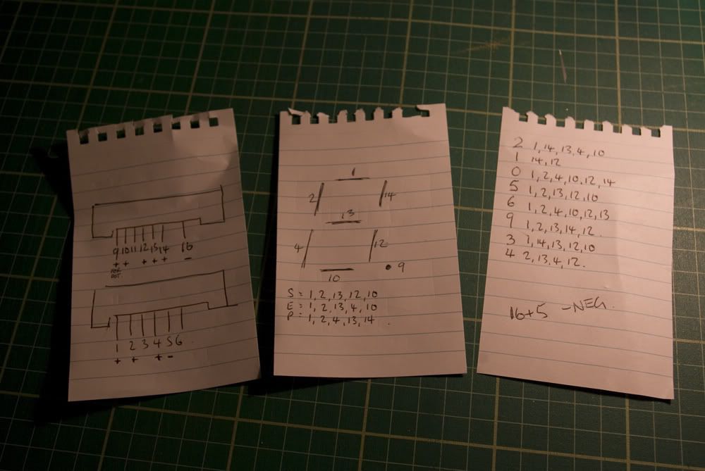
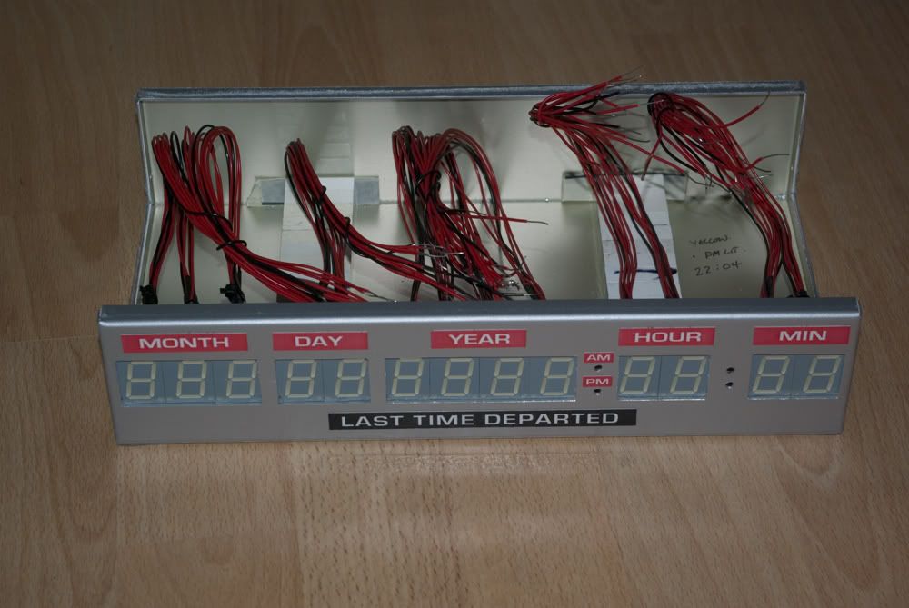
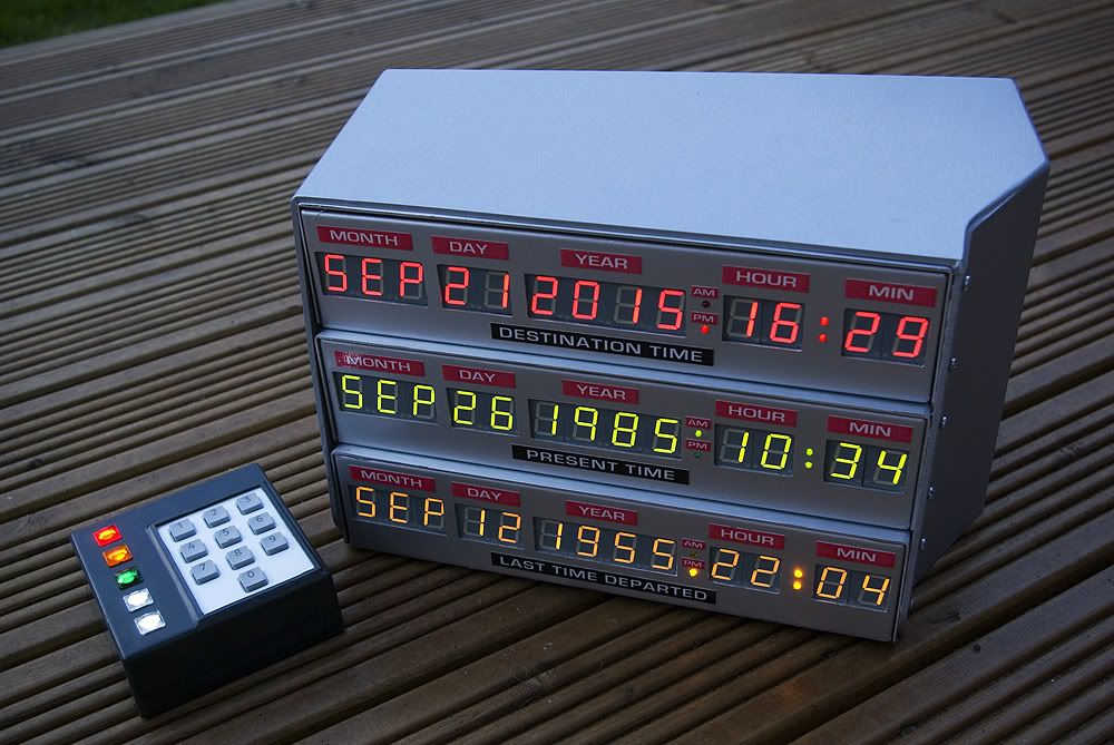
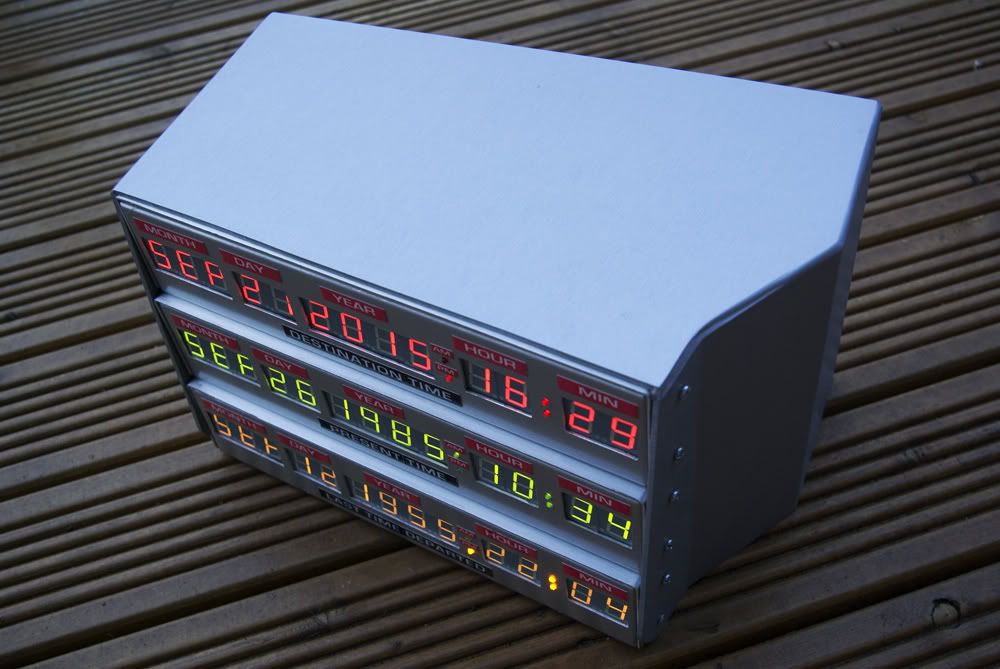
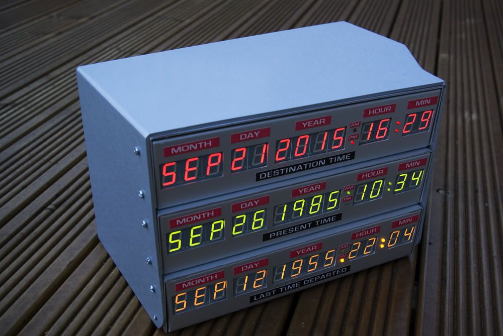
heres my take on the time circuits - yes im aware the size maybe a little larger than the original, times/dates not maybe accurate but the effect i got im very happy with i worked simply from screen grabs from the movie.

i was also unable to get alphanumeric segments in the uk - the only way i could meant buying 900 units and i only needed 9 - so the cost was too much to go and have 291 left unused.

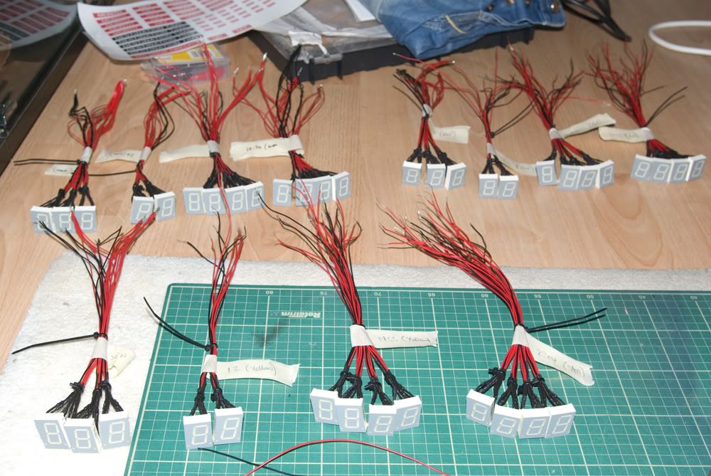
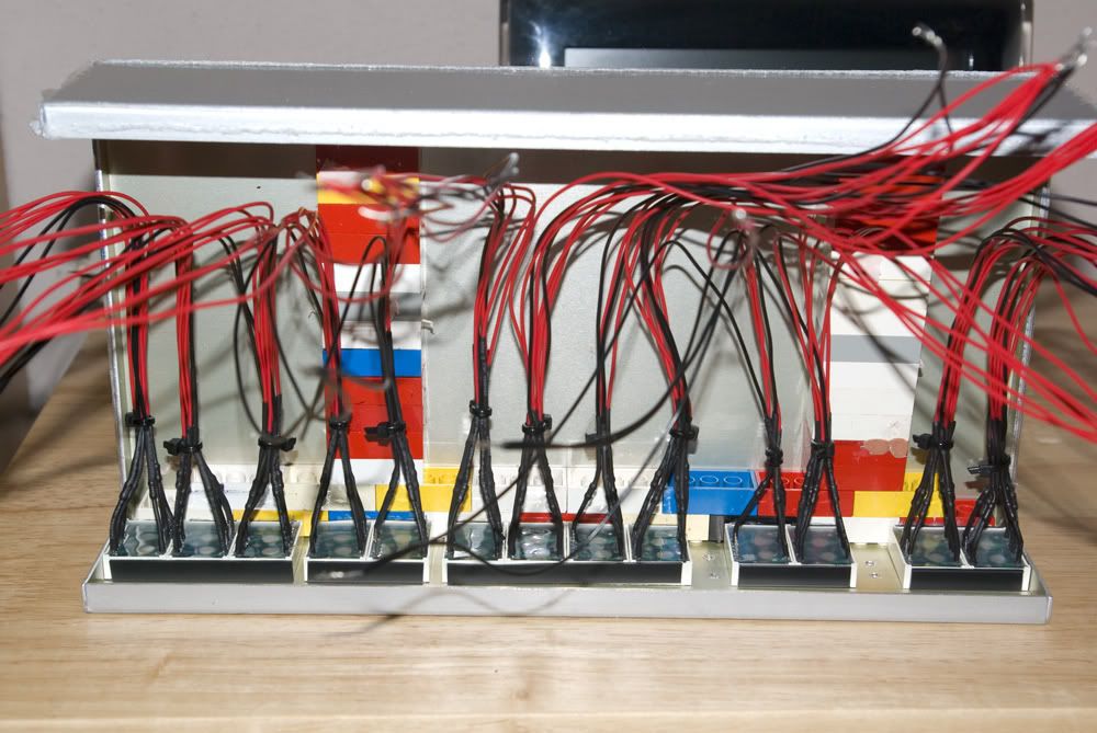
each segment was wired individually to get the relevent illumination, the boxes were the closest i could find to suit my needs, i jigsawed the holes out, filed them back, the outer casing was made from a material called dibond and was wrapped in conformable vinyl.

the keypad was scratch built from a keypad, project box, styrene and for the illuminated buttons i used 12mm acyrlic buttons.

so for the die hards amongst you i apologise if it is not 100% accurate, it was just a fun project for me to do esp given some limitations

the result and the other items in my collection i made (roentgens were bought as cost was cheaper):
73finished.jpg

74finished.jpg

75finished.jpg

78finished.jpg

08-withcircuits.jpg

cab4.jpg

cab3.jpg

cab1.jpg

roentclose.jpg

fluxclose.jpg

and my prized posession - a chris lloyed, lea thompson and mj fox signed crew jacket

universalsigned.jpg
 
Last edited:
Very nice. :thumbsup

I do have one suggestion that might help the accuracy and should be really easy to do. Print the labels on the Time Circuit Display using the Microgramma Bold Extended font. That's what the screen used TCD had. :cool
 
900-9=293?

blonde moment lol 291 - didnt fancy having that many alhanumerics at a cost of £450 uk pounds sitting around unsellable)

and no way im making another of these lol
 
I do have one suggestion that might help the accuracy and should be really easy to do. Print the labels on the Time Circuit Display using the Microgramma Bold Extended font. That's what the screen used TCD had

i used to be a signwriter - but i have been out of work since october last year - if i had access to the printer id have done them in proper vinyl - but ive had to accomodate in the meantime until i can do them again :(

same with the dayton labels - i had to use chrome fablon as i had no access to the proper equipment or vinyl materials

the other thing i may decide on is to paint the front face of the boxes to get that hammerite look - i have the spray - just until the labels can be done properly with alot more contrast to the reds ive had to leave it as is for the time being :(
 
Wouldn't (900 - 9 = 991)? Do you mean (300 - 9 = 291)?

Confusing mathematics aside, it's a very well-made piece! I've been wanting to make a time circuit wall-display for a while now. Basically a wall clock to have next to my work bench. But I want to have it "usable", being able to key in different "Destination" times and "Last Time Departed" times.

Again, yours looks brilliant! ^_^
 
yes - wired the common cathode segments individually so it would display the number i wanted. took alot of soldering:
05decodingthepinouts.jpg


15digitswired.jpg


33digitsbondedin.jpg


54lasttimedepdbonded.jpg
 
Last edited:
Basically a wall clock to have next to my work bench. But I want to have it "usable", being able to key in different "Destination" times and "Last Time Departed" times.

i did look at what it cost to get this ready made from a prop maker - fixed digits like i made i saw on ebay for approx 750 usd, then i read somewhere a fully working unit with the ability to key in the dates was around 2500usd due to the complexity of the electronics

i built mine for about 175 uk pounds
 
I'll be posting an open source set of parts for BTTF cars soon, including all of the automation. It's going to be a long process.

I'm starting with the time circuits, but eventually planning to do a full set of modular pieces that can all interact.

Anyone with electronics / arduino / related experience, feel free to contact me :)

--buddy
 
Sorry to revive an old thread, but what who45 has done is exactly what I want to do! Just wondering if I could get a simple schematic on how you wired up the segments and what you used to power them. Thanks!
 
This thread is more than 11 years old.

Your message may be considered spam for the following reasons:

  1. This thread hasn't been active in some time. A new post in this thread might not contribute constructively to this discussion after so long.
If you wish to reply despite these issues, check the box below before replying.
Be aware that malicious compliance may result in more severe penalties.
Back
Top