A 2021 Sperry Odyssey

macropod80

Active Member
Thanks to member abitofcredit, the pivotal AE-35 prop from 2001 has finally been identified as a reworked Sperry aircraft gyrocompass.
So I'm finally able to build an AE-35.
Korean.jpg

(And yes, that guy with the spacesuit website said he identified it years ago, but he didn't ever actually reveal the details, did he?)
Sadly abitofcredit seems to have lost enthusiasm for now (I get that a lot) so I'm starting the prop from the outside in - the 'cased' black box version:
cover screws.jpg
rather than the 'opened up' unit seen being tested on the diagnostic table .
Ultimately of course I want to be able to take the cover off to reveal the insides - and poke it with a probe (also helpfully identified by abitofcredit) - so the interior and exterior specifications will inform each other as I go.
Do check out abitofcredit's original thread (First Project: The AE-35 Unit! Advice appreciated )to follow the discussion about nailing the exact model of gyro and finding gyros on evilbay. And there are lots of useful photos.

Step one: buy a Sperry and measure it to scale the case:
IMGP3749reduced.JPG

Living on the wrong (ie: best) side of the world, postage on this 3kg lump cost a fortune. So I intend to take things slowly to get the details correct. (Well I tend to go slowly anyway because it's hard finding the time and I'm easily distracted.)
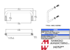
As I waited to find a Sperry I started working on a CAD model to help plan the construction:
comparison.jpg which is still proving helpful.
Finally, while stuck at home under Covid lockdown recently, I've managed to knock together most of a mockup over a weekend:
IMGP3737reduced.JPGIMGP3753reduced.JPGIMGP3754 (2)reduced.JPGIMGP3755reduced.JPGIMGP3757reduced.JPG
which has brought to light numerous issues I still have to resolve. (And since making the 'cased' AE-35 doesn't actually require a Sperry inside, I'll be providing the measurements and stl files I'm using for enthusiasts with less money to waste.)
Naturally I'd welcome any helpful suggestions, especially with identifying and sourcing parts and finding any better reference images. That shot at the top of Bowman in the Pod Bay, for example, isn't from the film - it's a still taken on set. Notice he's not actually standing at the test bench and there's a tarp or something on the floor behind him. I think this is cropped from a publicity still Dullea used to sign copies of at appearances or conventions but would love to see the full, higher resolution, image. Anybody have one?
 
Last edited:
Just jumping forward a few months:
One of many details I've been puzzling over on the inside is this 'something' where the cover screws onto the base:
cover mounting_LI.jpgzoom to 55_LI.jpg
And I think I've just got it. Months ago while scouring the Net for gyros I saw one in Germany that had something odd left stuck on a corner:
clipthing.jpgand it reminded me of little clippy things I'd seen, somewhere... which got an auto enthusiast friend to suggest "speednuts".
Which got me on to "Tinnerman clips".
Which is the answer.
Big in the military and aviation spheres; apparently used to be a home-handyman type of thing; lots of different types and plenty on evilbay:
Tinnerman fixings.jpg
Now I just need to find exactly the right one, or perhaps modify one that's close. Strange that they didn't just tap directly into that heavy aluminium bar that the clips are on. My guess is that they must have used self-tapping sheetmetal screws to hold the cover on, so they'd be quicker and easier to replace in this unused scene:
t front detail.jpg
My mockup's just using assorted left-over wood-screws, accumulated from IKEA stuff over the years.
 
Awesome progress. :)

As for the bottom rail - I interpreted the top-down photo from the movie as showing an aluminium bar with machined rectangular recesses in it. And then holes drilled into those recesses.

Are you suggesting that they had speed nuts inside the recesses?
 
Very nice work. I would be interested in whatever dimensions and drawings you are willing to share. I am also interested in building an all-up prop.

I also interpret photos as bars having pockets to hold speed nut type fittings.
 
As for the bottom rail - I interpreted the top-down photo from the movie as showing an aluminium bar with machined rectangular recesses in it. And then holes drilled into those recesses.
Well clearly I'm not seeing the world as others see it, which I confess is not a novel experience.
To my eyes, the aluminium bars along either side of the base have raised features on them. There are holes in the sides where you would expect them, but not just simple round ones.
Taking fuzzy photos is surprisingly tricky when you actually want to but I've experimented with a couple of bits of aluminium. The two little rectangles in that top-down photo:
cover mounting_LI.jpg I think look something like this:
Screenshot 2021-07-03 12201.jpg
(which I'm assuming is not quite so ambiguous)
Note the bottom edge - not the top edge - casts a shadow.
The view from the side gets more confusing when it's enlarged:zoom to 55_LI (2).jpg A round black hole appears to be drilled into the horizontal aluminium bar but is shaded by a surrounding rectangle with a vertical, arched slot in it. This rectangle appears to extend slightly above the top surface of the bar, perhaps bending back over it.
I would have expected the horizontal bar just needs to have two tapped holes to take the two screws visible on the outside of the cover. If it's more complicated, what for? Currently I'm guessing there's some sort of spring-steel clippy arrangement that allows a bit of lateral movement, so the cover doesn't need to be too precisely aligned in order for the screws to find their holes. This is what I'm thinking a Tinnerman fastener, maybe a speednut, could do. But I'm comfortable saying at this stage I still don't know. It's going to be a while before I get to making this part.
 
Last edited:
I think I may have the two cones on the back end a tad small, but I'm going to keep talking about the insides:
when I took that plate off the side of the gyro,IMGP3767red.JPGI was disappointed to find nothing underneath.I was expecting it to be covering a little vertical circuitboard as seen in the film:
ae35-fisheye.jpg

but there is a flat spot for it to be mounted on, with a screw and a screwhole to fix it with:
IMGP3771red_LI.jpgAnd there's a potential candidate in the correct spot on the gyro's opposite side:IMGP3765red.JPG
which does seem to be missing in the film:other side!.jpgBut while I can't see what is on the relocated board, it doesn't appear to be those two big, shiny capacitors.

So now another plea for help: here's an image with a better view of that little circuitboard:
14731383805_00d857cf1a_b.jpg
does anyone out there know what this image has been cropped from?
It's obviously not a frame grab from the film, but the position of the inner gyroscope matches those B&W stills found in the Getty Archive. So it may be from a colour version of one of those, but I haven't been able to find it anywhere. And before anyone asks, I found that picture on the website of that guy who years ago said he'd found the gyro, with a photo of his found example, which wasn't quite correct, but did seem to have the correct little circuitboard on the side!
AE-35%20gyro120.jpg
 
Interesting theory about the bar details. I'll have a think about that.

This is the shot you want. Sadly not the highest quality.

View attachment 1472886
Thanks for that nkg. According to Google, apparently it doesn't exist anywhere on the Internet - no wonder I couldn't find it!
Here's another intrigueing observation:
unit 2 variation.jpg
Those two Getty photos of a different unit (both with inverted top-plate graphics) show that one seems to be missing the cover attatchment features completely, including the brass screws holding down the aluminium bar! Looks like they were rehearsing the scene well before the prop was finished?
Progress is still slow because the research is so time-consuming. Having trouble finding a 4inch chrome/shiny 'D' handle for the front. Apparently the electrical term is a 'rack' handle. Furniture ones on this side of the world only come in 96mm for some reason, and are too fat at 3/8 inch dia. In the UK Hammond make a range: Chassis Handles (1427 Series) but none seems quite spot-on and I really want to see one first to be sure of the quality of the bend (needs to be smooth and around 1/2 inch radius- wider than most). As always postage is the killer.
 
Those handles are 0.313" in diameter, or 8mm.
 

Attachments

  • Screenshot 2021-07-05 at 15.10.42.png
    Screenshot 2021-07-05 at 15.10.42.png
    98.5 KB · Views: 57
A quick and dirty comparison suggests that the original handle was lower (shorter), with slightly thinner wires, and a slightly wider curvature.

I think the Hammond part could probably be cut down in height and it'd be close enough.
 
Detail on the red side board thing. Visconol-X is a brand of capacitors made by the Telegraph Condenser Co of London. Probably electrolytic here. The thing above it reads "TCC".

1625515497851.png
 
Last edited:
Alright folks, lots to digest here. I think that the macropod80's Sperry is not the same kind of model as the one on screen. The 3 ''buttons'' on the face have some kind of slanted piece on top of them. Macropod's ones are flat and have a shapely form.
Maybe that's why we have some missing details: i.e. the lack of those wires at the bottom. And again, I'm sure the prop master added/removed some parts that were not standard on that gyroscope...interesting research for sure!
 
A quick and dirty comparison suggests that the original handle was lower (shorter), with slightly thinner wires, and a slightly wider curvature.

I think the Hammond part could probably be cut down in height and it'd be close enough.
I think the 0.31" diameter looks better than the 0.38", but only the fatter ones come in lower than 1.5". I've guessed about 1 1/4", so yes, the taller one could be cut down. I reckon the bend is more like 1/2" radius, which isn't specified in the Hammond specs, but they look sharper. May have to settle on one of these if I find nothing better. Just have to find a local stockist.
I've just tried swapping that little circuitboard to the other side:
IMGP3777 (2)red.JPGIMGP3774red.JPGHad to lose a couple of capacitors (made by Plessey on this one) and the wires will need tidying, but it looks promising. May have to lose that last capacitor too, but the two silver posts it's between look like they match the film prop. I can imagine they took the capacitors off because they were so recognisable as not very futuristic.
 
Last edited:
I've traced over one of the photos from the side and dropped it, in blue, over the Hammond specs. I agree - it looks like the height is exactly 1.25" assuming a 4" hole spacing. The curve of the handle is also larger than the Hammond product. But I think it's probably okay if the height is cut down.
Screen Shot 2021-07-06 at 10.08.02.png
 
Alright folks, lots to digest here. I think that the macropod80's Sperry is not the same kind of model as the one on screen. The 3 ''buttons'' on the face have some kind of slanted piece on top of them. Macropod's ones are flat and have a shapely form.
Maybe that's why we have some missing details: i.e. the lack of those wires at the bottom. And again, I'm sure the prop master added/removed some parts that were not standard on that gyroscope...interesting research for sure!
I agree I've always felt those three round things don't look quite the same - they seem sharper-edged on top. But I think the lighting and angle make a big difference too. Still, I'm not throwing mine away and buying another, even if it does look ever-so-slightly more precisely the same. It's only a model...
 
These Haefele ones are similar to the Hammond, but lower. I think I'll get one of these as they're cheap and seem pretty close. 8mm diameter, 4" hole spacing, 30mm/1.2" height.


Only problem is that they also have the tighter handle radius than the original. But I don't think the handle is a critical enough part to warrant paying someone to make a bespoke handle.
 
Last edited:
I had a rod of the same thickness, but as you saw, my handle is 6''high:( The cost of just bending that rod came to $45 (Canadian $).
 

Your message may be considered spam for the following reasons:

If you wish to reply despite these issues, check the box below before replying.
Be aware that malicious compliance may result in more severe penalties.
Back
Top