Gentlemen,
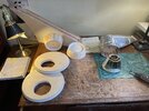
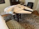
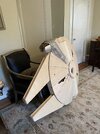
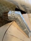
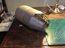
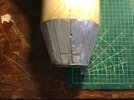
Took a break from initial skinning of the disc & mandibles. Can understand why the veterans on the 5 ft. model prefer blown plexiglass saucers. Attached some “raw construction“ of the cockpit cone.
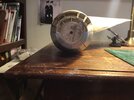
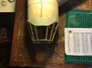
Changed out the wooden mock-up widow frames to brass and wanted to see how my .032 aluminum armor technique will work out. Using ratio method from the Bandai model to determine segment dimensions. Note the picture of the engineering paper used as a pattern for the cockpit skull cap. May need to take a 3D printing class since I can clearly appreciate how the computer calculates the little squares to get the curved measurements. If your measurements are “wonky” just a little, the squares tell you.
Not sure this model will qualify as a 5 ft. Studio Scale ANH MF given my approach to the project. But, it’s design is worth the effort and I enjoy the challenge. If any of you know a good number for the width of the channel that runs down the centerline of the cockpit and cone body, it will help when I get to the armor platting in that area so that sufficient space is provided for greeblie detail in this long run. Many measurements I can ratio or estimate along with this site’s threads, but under estimating this, by trusting Bandai and my math, is too risky. Again, I know that kit parts & 3D greeblies are required for fidelity. However, my major goal is airframe accuracy.
")