You are using an out of date browser. It may not display this or other websites correctly.
You should upgrade or use an alternative browser.
You should upgrade or use an alternative browser.
4' (AKA 5 foot) Falcon build
- Thread starter RealDaveWinter
- Start date
Lt Washburn
Sr Member
Awesome, thanks for sharing!
Sharing is caring -- this is appreciated, greatly.
Yes thanks for Sharing Dave, with that and all of your other reference Photos, it will definitely help when it comes time for me to do the Traditional Cockpit model for my 3d printed project. (If that is OK with you) Had quite a few requests for that one already 
Last edited:
I believe I have found the make/model of the fan in the back of the cockpit.
Rotron AX2HT-115-464YH
There are quite a few to be found on eBay but I purchased this one;
Rotron AX2HT-115-464YH
There are several variations of this fan;
The YH at the end indicates single phase AC. If you find one listed as JH, that's 3 phase AC, which is probably not what you want. It would seem odd for ILM to use 3 phase, but as there's no way to see the label for the fan, or any of the internal wires, I'm going to assume they kept it simple and used single phase. In any event, outwardly the fans are identical, so it wouldn't really matter which way you chose to go.
These fans are still in production because they are used in aircraft avionics. And as some avionic units were made in the 60s, replacement fans need to be identical to maintain the aviation type design and their air worthiness cert. (I'm an AME-S, it's my job to repair aircraft to their original type design)
Also, because these fans have an aviation cert, they can be very expensive. Try and find old ones that do not come with an aviation certification included. They would be about $70, rather than $400.
The attached PDF is the datasheet and drawing for newly manufactured ones. As aviation documentation needs to be kept current, the original drawings from the 60s/70s probably wouldn't qualify anymore.
These fans are 2.14" in diameter. There is another variation of this fan that is 3" in diameter, but based on limited photo evidence, I think the 2.14" fan is correct.
If someone has any corroborating or opposing information, please let me know. Otherwise I am going to say that this is the fan that was used. Hopefully this is new information and someone doesn't come out of the wood work and say 'well yeah, we all knew that...'
I still have no information on the engine deck fans.
Because my cockpit was designed to be modular, once my order arrives, I'll update it to use the correct fan in the back.
[edit] also, I need to shout out to Dazza007, as it was his ChatGPT log that put me on to Rotron


Rotron AX2HT-115-464YH
There are quite a few to be found on eBay but I purchased this one;
Rotron AX2HT-115-464YH
There are several variations of this fan;
The YH at the end indicates single phase AC. If you find one listed as JH, that's 3 phase AC, which is probably not what you want. It would seem odd for ILM to use 3 phase, but as there's no way to see the label for the fan, or any of the internal wires, I'm going to assume they kept it simple and used single phase. In any event, outwardly the fans are identical, so it wouldn't really matter which way you chose to go.
These fans are still in production because they are used in aircraft avionics. And as some avionic units were made in the 60s, replacement fans need to be identical to maintain the aviation type design and their air worthiness cert. (I'm an AME-S, it's my job to repair aircraft to their original type design)
Also, because these fans have an aviation cert, they can be very expensive. Try and find old ones that do not come with an aviation certification included. They would be about $70, rather than $400.
The attached PDF is the datasheet and drawing for newly manufactured ones. As aviation documentation needs to be kept current, the original drawings from the 60s/70s probably wouldn't qualify anymore.
These fans are 2.14" in diameter. There is another variation of this fan that is 3" in diameter, but based on limited photo evidence, I think the 2.14" fan is correct.
If someone has any corroborating or opposing information, please let me know. Otherwise I am going to say that this is the fan that was used. Hopefully this is new information and someone doesn't come out of the wood work and say 'well yeah, we all knew that...'
I still have no information on the engine deck fans.
Because my cockpit was designed to be modular, once my order arrives, I'll update it to use the correct fan in the back.
[edit] also, I need to shout out to Dazza007, as it was his ChatGPT log that put me on to Rotron


Attachments
Last edited:
Lt Washburn
Sr Member
Fantastic! Pun was literally not intended, but welcome.
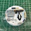
Well, just about completed the first of the 8 mandible mechanical pits. This is probably the easiest to do of the bunch. If you have done any of the other major parts, you probably have all the kits you need for this one. The only casting is the Sealab part, simply because I had a bunch of these cast and it saves the real part for some place else where it would be more obvious.
I've left the 'notch' in the tub so that it fits around the aluminum bar that goes inside the mandible.
I think this looks the part and matches up to the Bandai dimensions pretty closely. Probably not 100% perfect, but I think I got it very close.


I've left the 'notch' in the tub so that it fits around the aluminum bar that goes inside the mandible.
I think this looks the part and matches up to the Bandai dimensions pretty closely. Probably not 100% perfect, but I think I got it very close.


joberg
Legendary Member
Beauty all the wayWell, just about completed the first of the 8 mandible mechanical pits. This is probably the easiest to do of the bunch. If you have done any of the other major parts, you probably have all the kits you need for this one. The only casting is the Sealab part, simply because I had a bunch of these cast and it saves the real part for some place else where it would be more obvious.
I've left the 'notch' in the tub so that it fits around the aluminum bar that goes inside the mandible.
I think this looks the part and matches up to the Bandai dimensions pretty closely. Probably not 100% perfect, but I think I got it very close.
View attachment 1878878View attachment 1878879
I used a hairdryer and some really small clamps.This is part of the Airfix Harrow that is required around the sidewalls of one of the mechanical pits. It needs to be curved. However this plastic is extremely brittle. Any suggestions on how to best bend this plastic without it shattering? How have others done theirs?
thanks
View attachment 1879584
I ran mine every cm over a very lightly raised saw blade kerf and made it flexible in back with 8-10 shallow slices on the back (i.e., hidden) side of the pieceThis is part of the Airfix Harrow that is required around the sidewalls of one of the mechanical pits. It needs to be curved. However this plastic is extremely brittle. Any suggestions on how to best bend this plastic without it shattering? How have others done theirs?
thanks
View attachment 1879584
Thanks. For things like this in the past I've put the part into boiling water for a few minutes. But also just wanted to check to see what technique others had used with success in the past before I did anything.
So a question regarding one of the mech pits on the port mandible.
The part I've indicated is #74 from the Sealab (43); does a photo exist of the other side of this? The PG Bandai kit indicates that there's another of those parts on the other side, but I haven't found a photo to confirm.
Also, I'm not sure who's strand of hair that is laying across the model
thanks
Thanks.
But let me clarify, I'm looking for what is on the other side of part 74 specifically. My assumption is that it's just the other part 74 in the kit (that's what Bandai's PG kit says too).
Based on how the model is displayed when it's on tour, it might not be possible to get an angle that allows you to see that.
It sure doesn't look like much is there. My guess would be the other matching part.Thanks.
But let me clarify, I'm looking for what is on the other side of part 74 specifically. My assumption is that it's just the other part 74 in the kit (that's what Bandai's PG kit says too).
Based on how the model is displayed when it's on tour, it might not be possible to get an angle that allows you to see that.
I'm guessing Paul Huston's hair, given the length.So a question regarding one of the mech pits on the port mandible.
The part I've indicated is #74 from the Sealab (43); does a photo exist of the other side of this? The PG Bandai kit indicates that there's another of those parts on the other side, but I haven't found a photo to confirm.
Also, I'm not sure who's strand of hair that is laying across the model
thanks
View attachment 1880897
Huston is still alive, and still working for Lucasfilm, to the best of my knowledge.
Extra credit for 'super-accurate reproduction of the Falcon' if you can acquire one of these for your build.
I'll be selling mine on Ebay in a forthcoming auction... I didn't like the strand he sent me, as it was already gray and not at all accurate to the original.
I mean, yes, of course you can dye it to match the original, but that's such an obvious cheat that no one would fall for it, because that's the kind of cheat that shows up on an electron microscope... it'd be worse than using TeX Gyre Heros instead of Helvetica 6-point for the lettering of the names, and you'd lose your credibility in the studio scale modeling community almost overnight...
; )
It sure doesn't look like much is there. My guess would be the other matching part.
Thanks, yeah, that's not going to be an angle most people are going to see. Bandai calls for it to be two part 74's back to back, and so that's what I've gone with. That kit has certainly gotten things wrong before, but this is probably a safe route to go.

