A small update on my build for those interested. Things have been a bit slower than I would like, but I'm still getting things done.
I'm planning on making some changes and updates to the cockpit, specifically the fan in the back. Now that I have the correct fan on order, I'm going to rework that part of the build.
Most of the past little while has been on the mandibles. Specifically the 8 mechanical pits.
The tubs themselves are made from 1mm sheet styrene. I added a 3mm strip around the top edge simply to provide a little bit more gluing surface. The four that are squared off are done so to accommodate the aluminum tube that goes through the mandible structure. ILM did the same thing.
Port - Lower - Forward
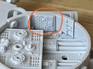
90% complete. There's a small 'gear' like part that I'm missing. I've not figured out what kit it comes from, if it comes from a kit at all. It may be an actual gear, but based on some up close photos, I'm not convinced of that. The part maps call for it being N45 of the Hummel, but that's not correct. N45 is much too small. If anyone can confirm if it's a kit part, or an actual gear, that alone would be helpful.
View attachment 1888856
Starboard - Upper - Rear
Complete. Just the one casting here. I made it from the original part, but I am not sure if that part is used in other places yet, so I made a cast instead of using the real part.
View attachment 1888855
Starboard - Lower - Rear
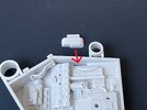
90% complete. Just missing the Elephant part, lower right. The kit is currently stuck in some Canada Post depot so I guess it shows up when it shows up after the strike is over. Thanks to
Shamon for helping get the orientation of the Scammel part correct. The Bandai PG kit is very helpful, but you really do need to triple-check photo references. Either on purpose or by accident, the Bandai kit does have some things wrong.
View attachment 1888857
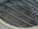
Port - Upper - Forward
Complete. Just the one casting here as well. The Sealab grill lower left. I have pretty much cast the complete Sealab kit at this point.
View attachment 1888858
The Others
The remainder four are all waiting on parts before I start assembling, but I've gathered what I do have into the little tubs I made. I'm trying to source the one kit that is required for the top two. I know the kit I need, I just can't find one for sale.
The other two, on the bottom, have kits on the way but they're currently stuck with Canada Post.
View attachment 1888859
So, there's where I am. I'm off until January, so hopefully I can make a bit of progress on this beast.
thanks for looking.