You are using an out of date browser. It may not display this or other websites correctly.
You should upgrade or use an alternative browser.
You should upgrade or use an alternative browser.
1/24 X-Wing near 100% from scratch
- Thread starter Moska
- Start date
Moska
Sr Member
Hi Retep1701a and ssfx.
Many thanks for your support and for following my thread.")
Ryder, you can be sure of that.
In those glorious 70's, IL&M modelers could be free to pick, cut, join and place kits parts at their discretion.
Now, those models are cultural icons, and to make a good replica must be very precise and exact when you copy everything they did (what's a real great pleasure for a scratch modeler).
Many thanks for your kind words about my work.
I'm currently working on dressing the rear engines.
New pics coming soon.
Rafa
Many thanks for your support and for following my thread.
I'm sure this point has been made before (though I've not seen it)... but it's far, far easier to produce the original model, than it is to produce a replica of it... I'm truly in awe by what you are accomplishing here.
R
Ryder, you can be sure of that.
In those glorious 70's, IL&M modelers could be free to pick, cut, join and place kits parts at their discretion.
Now, those models are cultural icons, and to make a good replica must be very precise and exact when you copy everything they did (what's a real great pleasure for a scratch modeler).
Many thanks for your kind words about my work.
I'm currently working on dressing the rear engines.
New pics coming soon.
Rafa
Moska
Sr Member
Hello friends.
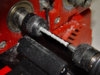
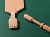
As I said in previous post, I'm currently working on the details that complete the rear engines.
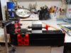
Both the Frog Whitley part, as the one from Nitto / Fujimi Jagdpanther has given me the opportunity to return to work with my old and loyal UNIMAT mini lathe.:love
To operate these so small pieces, I helped with my also old and loyal X-ACTO magnifying glass.
I've mounted the magnifying glass on the lathe using a piece of padded tape with two selfadhesive faces, and it works well for my purposes.
Once the Whitley part was finished, I've noticed that turned parts are too thick, so I'm currently working again to build a new piece more closer to the original. :behave
I Take this opportunity to consult a doubt, does anyone knows from where originally came the front closures of the rear engines?
You know, those conical ends that goes into the Saturn-V pieces. :confused
Many thanks for looking.
Rafa
As I said in previous post, I'm currently working on the details that complete the rear engines.
Both the Frog Whitley part, as the one from Nitto / Fujimi Jagdpanther has given me the opportunity to return to work with my old and loyal UNIMAT mini lathe.:love
To operate these so small pieces, I helped with my also old and loyal X-ACTO magnifying glass.
I've mounted the magnifying glass on the lathe using a piece of padded tape with two selfadhesive faces, and it works well for my purposes.
Once the Whitley part was finished, I've noticed that turned parts are too thick, so I'm currently working again to build a new piece more closer to the original. :behave
I Take this opportunity to consult a doubt, does anyone knows from where originally came the front closures of the rear engines?
You know, those conical ends that goes into the Saturn-V pieces. :confused
Many thanks for looking.
Rafa
Attachments
Moska
Sr Member
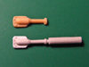
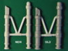
Well, my second version of the FROG piece is finished. In the images may not appreciate well the difference between old and new, but really looks best when the new piece is into place.
The same thing happened with the part of the JAGDPANTHER. My first attempt was too thick and again I had to do a second version. :behave
The part to create the rear engines is finished now.
After some months of work, my project is taking shape and there are more pieces in my drawer, ready to be placed on my X-Wing.
Thanks for looking.
Rafa
Attachments

Ryder
New Member
That little lathe of yours sure seems to be doing the trick... are you holding the cutting tool by hand? Who produced your lathe?
You know, my friend... this might be the best x-wing ever produced when you're done, even better than IL&M in terms of overall quality. Of course since you are doing a replica of their original, you'll never equal their relative lack of quality
Ryder
You know, my friend... this might be the best x-wing ever produced when you're done, even better than IL&M in terms of overall quality. Of course since you are doing a replica of their original, you'll never equal their relative lack of quality
Ryder
Moska
Sr Member
Hi Ryder.
Thank you very much for your kind words.
Yes, I control the cutting tool manually. It's a very basic lathe but is a good help and does a good job.
My lathe is EMCO brand. An Austrian company that ceased business some years ago. If you want more information, visit the following link:
The Cool Tool GmbH - Home of Unimat1, child friendly model making and professional prototyping
Thanks for looking.
Rafa
Last edited:
Moska
Sr Member
Hi Andre.
Thank you very much for your kind comment.
For me, working focused on these small pieces and trying to be as accurate as possible, is good therapy to forget and to rest for a moment of the economic crisis here in Spain.:wacko
Hey! tell to Angela Merkel that don't be so demanding.:lol
Best regards.
Rafa
el loco
Well-Known Member
Hi Andre.
Thank you very much for your kind comment.
For me, working focused on these small pieces and trying to be as accurate as possible, is good therapy to forget and to rest for a moment of the economic crisis here in Spain.:wacko
Hey! tell to Angela Merkel that don't be so demanding.:lol
Best regards.
Rafa
Yeah, i will talk to her :lol
Moska
Sr Member
Hello friends.
I'm preparing to work in the canyons of my X-Wing and it's time to buy the Plastruct tubes I need.
But I have a question: what material is most suitable, ABS or butyrate? :confused
I've never worked with butyrate, so I don't know what their advantages and disadvantages.:confused
Any advice?
Thank you very much in advance.
Rafa
I cannot offer any advice on the butrayte as I have never worked with it. The original cannons were made from brass tubing.
You could always continue to work in styrene. You have done an amazing job with this project and I have no doubt whatever you choose will wind up looking great.
You could always continue to work in styrene. You have done an amazing job with this project and I have no doubt whatever you choose will wind up looking great.
Moska
Sr Member
The original cannons were made from brass tubing.
Hi Nighteyes.
I'm talking about the bodies of the cannons. Of course, the best option for the thin parts of the cannons is to use telescopic brass tubing to ensure that they are perfectly straight.
I did a search on the forum and I see that almost all modelers have used butyrate, so I will buy tubes of this material. I always prefer to use styrene, but no styrene tubes with the diameters that are needed.
:confusedCan anyone tell me what's the right glue to paste the butyrate? :confused
I understand now.
We need input from MonsieurTox!
We need input from MonsieurTox!
darth_myeek
Sr Member
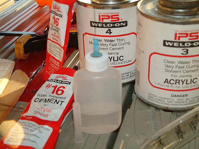
Here are a couple of solvent based glues, but you'd definitely want to test this solvent cement method on scrap. It's thin like water, so too much will puddle possibly marring the finish of a surrounding surfaces. "Capillary action" means to apply it near the edge of the mating surfaces and the liquid will draw itself between the parts.
==============================
Plastic Weld solvent cement Hobby sized.
* The leading general purpose solvent cement for fast, permanent bonding dissimilar plastics. Immediately tacky. Sets in minutes. Cures in hours. Permanently bonds most common plastics. Actually dissolves a thin film of the surfaces to be joined, creating a bond as strong as the surrounding areas. Also works as a liquid filler. Full coverage by capillary action. Applicator brush in cap.
Permanently Bonds:
ABS to ABS
ABS to Acrylic
ABS to Butyrate
ABS to Styrene Butyrate to ABS
Butyrate to Acrylic
Butyrate to Butyrate
Butyrate to Styrene Styrene to ABS
Styrene to Acrylic
Styrene to Butyrate
Styrene to Styrene
==================================
Weld-On
Here is a more economical version but more importantly a better method for dispensing. (needle bottle applicator). A trick is to squeeze a 1/3rd full applicator bottle before inverting and then to allow the bottle's suction to control flow.
Moska
Sr Member
Hello darth_myeek.
Thank you very much for your input. It's always a problem to know what are the best products to work on a new material.
I will seek that kind of glue ... as long as the guys in EMA-MODELS.CO.UK kindly respond to my requests. I sent them twice a shipping fee request to get the butyrate tubes at my home but I get no response.:angry
------ UPDATE -------
Two new pieces completed.
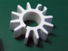
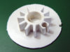
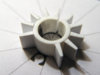
After my failed attempt to get the heatsinks by laser cutting, I decided to build a master for subsequent copies in resin.
First I got a plastic tube of the correct diameter, and then I did the fins using 1.5 mm. styrene sheet and, with the help of a printed template as guide, I stuck them around the tube.
Then I carved the remaining piece on a block of 7 mm. thick styrene and stuck it also on the central tube.
Finally, I pasted the group on a piece of 0.5 mm. sheet styrene piece to strengthen it and get a better finish when sanding the upper and lower sides for to get the right thickness.
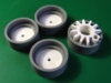
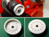
The rings of the cannons, which originally comes from the Bandai kit 1/15 Hummel, I built a master starting from a central plastic tube and a outer tube, joined by a circle of 1 mm styrene.
Using my mini-lathe again, I worked on the outer tube to give it its conical shape, both on the outside of the tube itself as its base.
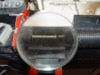
The next piece that I build is the rear of the cannons.
Does anyone know the donor kit of that circular piece? :confused
It seems clear that is a wheel of some tank, but I don't know wich specifically.
Thanks for looking.
Rafa
Thank you very much for your input.
It's always a problem to know what are the best products to work on a new material.I will seek that kind of glue ... as long as the guys in EMA-MODELS.CO.UK kindly respond to my requests. I sent them twice a shipping fee request to get the butyrate tubes at my home but I get no response.:angry
------ UPDATE -------
Two new pieces completed.
After my failed attempt to get the heatsinks by laser cutting, I decided to build a master for subsequent copies in resin.
First I got a plastic tube of the correct diameter, and then I did the fins using 1.5 mm. styrene sheet and, with the help of a printed template as guide, I stuck them around the tube.
Then I carved the remaining piece on a block of 7 mm. thick styrene and stuck it also on the central tube.
Finally, I pasted the group on a piece of 0.5 mm. sheet styrene piece to strengthen it and get a better finish when sanding the upper and lower sides for to get the right thickness.
The rings of the cannons, which originally comes from the Bandai kit 1/15 Hummel, I built a master starting from a central plastic tube and a outer tube, joined by a circle of 1 mm styrene.
Using my mini-lathe again, I worked on the outer tube to give it its conical shape, both on the outside of the tube itself as its base.
The next piece that I build is the rear of the cannons.
Does anyone know the donor kit of that circular piece? :confused
It seems clear that is a wheel of some tank, but I don't know wich specifically.
Thanks for looking.
Rafa
Attachments
Moska
Sr Member
Hi Stu.
Thank you very much for your comment. Yes, I'm happy for the result of the heat sink. I love when things go right at the first try.:cheers
And also thank you very much for the part id. It's the last that I had not identified on the outside details. :cheers (why not a second one?)
--------
The butyrate tubes are on their way to my house. Now I need to get the brass or aluminum tubes for the thinner parts of the canyons.
My project is going smoothly.
Rafa
Moska
Sr Member
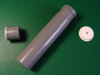
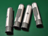
New updates.
I decided to work again on the ring of the guns to make the step that shows on its outer surface.
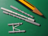
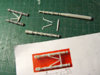
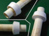
The rear cover of the guns was easy to build with the help of my mini-lathe.
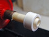
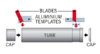
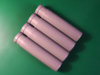
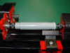
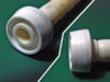
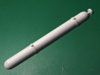
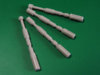
I used again my mini-lathe to make the main bodies of the guns. As the mini-lathe is very basic and I have no clamps for large diameters, I had to make a plastic caps that fits well in the pipe ends to fix them on the lathe.
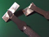
Also, I made a small aluminum templates on which I paste the cutting blades which helped me to make the four equal bodies. The templates limited the depth to which the blades could go, making it easier to work.
I have also finished the larger rings that goes in the front of the main body.
Thanks for looking.
Rafa
I decided to work again on the ring of the guns to make the step that shows on its outer surface.
The rear cover of the guns was easy to build with the help of my mini-lathe.
I used again my mini-lathe to make the main bodies of the guns. As the mini-lathe is very basic and I have no clamps for large diameters, I had to make a plastic caps that fits well in the pipe ends to fix them on the lathe.
Also, I made a small aluminum templates on which I paste the cutting blades which helped me to make the four equal bodies. The templates limited the depth to which the blades could go, making it easier to work.
I have also finished the larger rings that goes in the front of the main body.
Thanks for looking.
Rafa
Attachments
-
 larger_rings.jpg104.5 KB · Views: 441
 -
 how_to_cannons_bodies.jpg51.7 KB · Views: 476
 -
 cannons_bodies.jpg116.9 KB · Views: 414
 -
 blades_on_templates.jpg157.9 KB · Views: 418
 -
 caps_on_lathe.jpg107 KB · Views: 436
 -
 caps.jpg94.4 KB · Views: 405
 -
 m8carrier-04.jpg121.2 KB · Views: 424
 -
 hummel-11.jpg143 KB · Views: 387
Moska
Sr Member
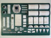
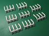
New updates:
1. - I finally got the suitable vinyl for paneling the bodies of the cannons. There is a wide range of vinyl tape and isn't easy to find the appropriate thickness. I asked a friend who works in a signage company, and they use a type of very thin vinyl for cutting plotter. Too thin for my purposes. According to my friend, thick vinyl is poor quality and that's why they use the thinnest. I asked for a thicker vinyl and he advised me that they use for printing. Of course, only in white, but the thickness is right in my opinion.
2. - Once again I used my mini-lathe to make the Hanomag parts that go into the rear channel of the wings.
3. - I've also done the part from the Sealab kit that is like a gas cylinder and that is placed next to the wells of the internal motors.
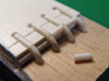
4. - Finally, I've also done the grill shaped pieces from the Sealab that are placed at both sides of the inner engines.
For inner engines, I preferred not to use the same parts used in the rear engines. To me it makes no sense to use the same parts in both areas. Okay, all four engines are equal, but isn't very logical that the pieces are the same in two such different areas of a single engine.
Fortunately, there are two different type of internal engine configuration, so I can choose which I prefer without losing accuracy.
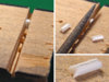
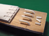
To make these pieces, which at first seem complicated, I made a simple template on a piece of wood and a piece of plastic that helps me to fix and align perfectly the four curved rods. I've also done a channel in the piece of wood with a hole in the center to hold the small parts that make crossbar. Once they are subject in that hole, and using the channel as guide, I can use a small round file to give the U-shaped at the ends of the crossbars so that fits well against the curved bars.
The small step I made in the plastic template helps me line up the crossbars.
First I use liquid glue to paste these pieces, so I can make small corrections and adjust their alignment perfectly, and once the unión is near dry, I further reinforced the area by using a few drops of cyanoacrylate on the bottom of such unions.
Thanks for looking.
Rafa
1. - I finally got the suitable vinyl for paneling the bodies of the cannons. There is a wide range of vinyl tape and isn't easy to find the appropriate thickness. I asked a friend who works in a signage company, and they use a type of very thin vinyl for cutting plotter. Too thin for my purposes. According to my friend, thick vinyl is poor quality and that's why they use the thinnest. I asked for a thicker vinyl and he advised me that they use for printing. Of course, only in white, but the thickness is right in my opinion.
2. - Once again I used my mini-lathe to make the Hanomag parts that go into the rear channel of the wings.
3. - I've also done the part from the Sealab kit that is like a gas cylinder and that is placed next to the wells of the internal motors.
4. - Finally, I've also done the grill shaped pieces from the Sealab that are placed at both sides of the inner engines.
For inner engines, I preferred not to use the same parts used in the rear engines. To me it makes no sense to use the same parts in both areas. Okay, all four engines are equal, but isn't very logical that the pieces are the same in two such different areas of a single engine.
Fortunately, there are two different type of internal engine configuration, so I can choose which I prefer without losing accuracy.
To make these pieces, which at first seem complicated, I made a simple template on a piece of wood and a piece of plastic that helps me to fix and align perfectly the four curved rods. I've also done a channel in the piece of wood with a hole in the center to hold the small parts that make crossbar. Once they are subject in that hole, and using the channel as guide, I can use a small round file to give the U-shaped at the ends of the crossbars so that fits well against the curved bars.
The small step I made in the plastic template helps me line up the crossbars.
First I use liquid glue to paste these pieces, so I can make small corrections and adjust their alignment perfectly, and once the unión is near dry, I further reinforced the area by using a few drops of cyanoacrylate on the bottom of such unions.
Thanks for looking.
Rafa
Attachments
-
 sealab-08.jpg158.1 KB · Views: 475
 -
 sealab-07.jpg179.3 KB · Views: 423
 -
 sealab-06.jpg182.9 KB · Views: 444
 -
 sealab-05.jpg147.5 KB · Views: 396
 -
 hanomag-01.jpg143.8 KB · Views: 429
 -
 cannons_bodies-03.jpg129.2 KB · Views: 395
 -
 cannons_bodies-02.jpg163.7 KB · Views: 459
 -
 sealab-09.jpg196.2 KB · Views: 471
Similar threads
- Replies
- 15
- Views
- 2,410