BTTF Futaba Delorean Remote Project

Mike,

How is your circuit board set up. Does it have integrated resistors for the LEDs or will you need to add them in?

I just realized I didn't upload any of the internal shots of the Unibox wiring. I'll try to dig those up tonight and post them here. Sorry about that.

-Gary

It has resistors on the board already that I had to solder in there spots.Im just not sure if there's a way to get your displays onto my board in place of the segments that are on it now.the segments for that board get put into pin headers soldered on the board which is a different set up on yours.I really would like to see how you wired yours.
 
Do you have any specific info regarding the LED displays that came with your original board? If they have the same voltage requirements then it should be as simple as figuring out the pin outs for your board and cross referencing them to the pins on the Stanley displays.

Since the resistors are already in place on the board all you will need to do is solder the stanley segment wires to the board.
 
My "board" is really nothing more than a piece bread board with a common power line. Each resistor comes off that shared positive power line and the wire for each stanley segment connects to a resistor. The three negative pins for the stanleys are all connected together and lead back to the negative terminal on the 9v battery. I don't think the negative even touches the board.

The middle segments for the 88 are wired to a second parallel power feed which is wired to a Normally Open Momentary Switch. That way, when I press the momentary switch on the side it closes the circuit and lights up the middle segments.
 
I hear what you mean.The problem is my whole board can't exceed 6 volts which I hope ain't a problem with your segments.the segments I'm using are regular 7 segment LEDs you can get anywhere.There are like 7 pins on each side left and right behind the segments.I need to get the model of the segment.
 
I'm hoping this is the case.
Do you have any specific info regarding the LED displays that came with your original board? If they have the same voltage requirements then it should be as simple as figuring out the pin outs for your board and cross referencing them to the pins on the Stanley displays.
.
 
Mike,

Are there any model numbers on your 7 segment displays? I'm suspecting they will work right across, but I recall reading that there can be slight differences in spec between red and yellow LEDs.

As promised a shot of my interior board. Like I said, it's nothing special and certainly not about to win any beauty contests. However, it gets the job done just fine.

View attachment 125552

View attachment 125553

-Gary
 
Thanks gary I'm in touch with that board creator and it seems I will be able to hook it up to your displays.I'm just trying to understand everything.I have the board working. I just need to get your display on it and I'm good to go.
 
Alrighty,

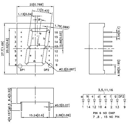
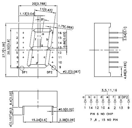
Here is a quick pin diagram for the stanley displays. Also, a rough schematic to show how I wired a typical single display. for all three units I just extended the common positive feed. In the previously posted pictures of the board, the common positive feed is behind the board/resistors.

pinouts.jpg

stanley-layout.jpg
 
Hello,
I designed the working board of Doc's remote, I made one Printed Circuit Board for Mike (Pitbull). I want to help him to make work the board with Gary Weaver 's Stanley Diplays but I have to know a important information. The board works with common Anode but I don't know if the board will work with the Stanley Diplays because I don't know if they are common Anode or common cathode.

My board works with this type of led displays (common Anode) :
sa08-11ewa.jpg


but it doesn't work with this type of led displays (common Cathode) :
sc08-11ewa.jpg


Question : The Stanley Displays are common Anode or common Cathode ?
 
Yes according to the drawing above, Common Cathode is what I thought but I would like a confirmation from the builder of the Stanley Displays.
 
Damien I'm positive your correct.Im sure gary will comment soon.Thanks for coming on here and helping out the situation.You and gary should get together and offer some kits ;) both of you are very talented at what you do.

I sent you an email Damien answering your question btw.

-mike
 
The two test boards I wired up for Mike and Brad were both common cathode (-). Not a problem with a static display, but it gets akward if you are connecting it to a circuit.

The original stanleys were actually grain of wheat bulbs (no leds). My circuit board was based on that design, but I designated a single common, which can be set as anode or cathode.

I guess I had a 50/50 shot of getting it right and landed on the wrong side of the coin :)

It's easily fixed though, I'll wire up a new board for Mike this weekend which will be common anode (as simple as reversing the LEDs). That should work fine with the existing board.

Damien, please send me a PM when you get a chance. I'd like to talk to you about some stuff and coordination on these things.

-Gary
 

Your message may be considered spam for the following reasons:

If you wish to reply despite these issues, check the box below before replying.
Be aware that malicious compliance may result in more severe penalties.
Back
Top