ozzyguanche
Sr Member
Hi all,
Its been a while since I last posted here or worked on a model, but fortunately I have reclaimed my weekends and have started a new project I thought I would share.
As some would know my favourite subject is the millennium falcon and in particular the 5 foot ANH version. I have made a few attempts to convert the old MPC kit to resemble the big falcon with some failures and some successes. Its been my ambition to re-create an MPC sized scale version of the 5 footer, so I thought I would have one more go.
With old calculations of my own and the plans created by vfxsup64's I am using some parts from the MPC falcon to rescale it to suit 144th, 15mm and 1/76 and 1/72nd kit parts. It turns out that dividing vfxsups64's plans by 3.5 matches some major areas of the MPC model, as long as you don't take the outer dome diameter of the MPC as being correct. The outer diameter of the MPC matched at this size the overhang of the plexiglass stage only. Increasing the size of the outer done of the MPC brings areas such as the mandables, turret domes, access pits etc to close to correct scale and position. The usual approach is to decrease everything on the MPC to suit the outer dome.
Anyway, I printed out scaled plans (made adjustments based on vfxsups64's measurements) and made two plates.

I spaced the mandibles to 1.5cm (includes thickness of plastic used for plates). I then used some downpipe to get the correct height of the two halves for the curvature of the hull. Had a lot of trouble with this so didn't take pics. Had to take into account thickness of materials used plus mandible heights to get the correct spacing. When working in millimetres its easy to forget a thickness or two so had to do it over a few times.
So next I cut up the old MPC falcon and used the hull parts to make the two dome halves and curve the pieces to the correct shape. I matched outer hull diameter of the MPC with the plexiglass (rescaled 3.5) diameter of the two halves.


I re-inforced the parts with some bolsa and foam core, and made sure the two halves matched. Then ensured the engine deck piece which will be removable like the original, fitted, which fortunately it did. In the second pic above you may see I inserted a rim inside the plumbing pipe to accommodate the turret. Pics below show the turret inserted. The MPC turret is the right size devided by 3.5. The outer rim still needs to be extended so it slopes but scale size is correct. The engine deck will be sanded down and engine vents repositioned for the scale change.


Next I cut the outer diameter off so only the inner diameter remains. I will run a new overhang diameter to represent the plexiglass overhang so the MPC plastic thickness will simulate the lip that runs the circumference of the dome.

As the plating will now be out of scale I have covered with an apoxi resin which I will sand down for a smooth finish and replate.

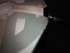
I have started on the jaws which have been difficult to make. Its not just a single straight side, but an angle outward and then parallel down to the dome.


The base of the jaw sits on the height of the lip created from the dome thickness. (if that makes any sense!!)

I will be working on the docking rings and walkways next weekend.
Thanks for looking.
Ozzy
Its been a while since I last posted here or worked on a model, but fortunately I have reclaimed my weekends and have started a new project I thought I would share.
As some would know my favourite subject is the millennium falcon and in particular the 5 foot ANH version. I have made a few attempts to convert the old MPC kit to resemble the big falcon with some failures and some successes. Its been my ambition to re-create an MPC sized scale version of the 5 footer, so I thought I would have one more go.
With old calculations of my own and the plans created by vfxsup64's I am using some parts from the MPC falcon to rescale it to suit 144th, 15mm and 1/76 and 1/72nd kit parts. It turns out that dividing vfxsups64's plans by 3.5 matches some major areas of the MPC model, as long as you don't take the outer dome diameter of the MPC as being correct. The outer diameter of the MPC matched at this size the overhang of the plexiglass stage only. Increasing the size of the outer done of the MPC brings areas such as the mandables, turret domes, access pits etc to close to correct scale and position. The usual approach is to decrease everything on the MPC to suit the outer dome.
Anyway, I printed out scaled plans (made adjustments based on vfxsups64's measurements) and made two plates.
I spaced the mandibles to 1.5cm (includes thickness of plastic used for plates). I then used some downpipe to get the correct height of the two halves for the curvature of the hull. Had a lot of trouble with this so didn't take pics. Had to take into account thickness of materials used plus mandible heights to get the correct spacing. When working in millimetres its easy to forget a thickness or two so had to do it over a few times.
So next I cut up the old MPC falcon and used the hull parts to make the two dome halves and curve the pieces to the correct shape. I matched outer hull diameter of the MPC with the plexiglass (rescaled 3.5) diameter of the two halves.
I re-inforced the parts with some bolsa and foam core, and made sure the two halves matched. Then ensured the engine deck piece which will be removable like the original, fitted, which fortunately it did. In the second pic above you may see I inserted a rim inside the plumbing pipe to accommodate the turret. Pics below show the turret inserted. The MPC turret is the right size devided by 3.5. The outer rim still needs to be extended so it slopes but scale size is correct. The engine deck will be sanded down and engine vents repositioned for the scale change.
Next I cut the outer diameter off so only the inner diameter remains. I will run a new overhang diameter to represent the plexiglass overhang so the MPC plastic thickness will simulate the lip that runs the circumference of the dome.
As the plating will now be out of scale I have covered with an apoxi resin which I will sand down for a smooth finish and replate.
I have started on the jaws which have been difficult to make. Its not just a single straight side, but an angle outward and then parallel down to the dome.
The base of the jaw sits on the height of the lip created from the dome thickness. (if that makes any sense!!)
I will be working on the docking rings and walkways next weekend.
Thanks for looking.
Ozzy

")


.jpg")


