Iron man motorised faceplate electronics tutorial!!!

1. It should be like in this datasheet http://www.produktinfo.conrad.com/datenblaetter/150000-174999/155785-da-01-en-TRANSISTOR_BC547B_TO92.pdf

2. it says its the pinouts are the same as 546/547/548

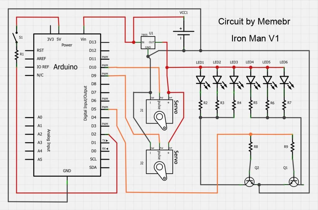
Yes battery pack is 7.4V regulated to 5V. connected the leds directly to the 5V rail.

I'll have to check it out when I get to work..

but thats NOT the same transistor "I" used.. (thats similar to the one memebr used).. follow his wiring diagram.. (if he has the collector, emitter & based labeled)
 
I'll have to check it out when I get to work..

but thats NOT the same transistor "I" used.. (thats similar to the one memebr used).. follow his wiring diagram.. (if he has the collector, emitter & based labeled)

Oh yeah that true. it similiar as member used.
Would be great if you could help me out though. TNX! ;)
 
I am using the Hitec HS-56HB as well. I have tried multiple servos, and I really like these. They are small, fast and do the job. They also have metal/composite gears. The torque is slightly less than some of the others but work fine on all my "cast" helmets. Havent tried them on any of my heavier fiberglassed/bondoed helmets but I dont think it would be a problem.

Awesome. I'm going to be buying a cast Patriot helmet so knowing those servos can lift a faceplate is reassuring.
 
XL,

i bought a npn BC547B transistor. Connected it the same as in your schematic, but the light were not bright at all. There was enough power going in. i dont understand.
Then i directly connected the postive and negative cable to my (5v)positive and negative rail on the breadboard. The light were bright as the should be.
But then i noticed the VREG was getting really hot?

What am i doing wrong?????

A fill things i need to know before giving you an answer:

Did you use a resistor for the base? the base cant handle much current, you need to limit this current from the arduino, try using a 2.2Kohms resistor on the base, if it is still not as bright as you like, drop that resistor value to something a lil lower than 2.2K

Is the load linked to the collector of the transistor?

follow this for NPN transistors and you will never be wrong again:

The collector collects the load and pass it to the emitter, the emitter emits it to the GND, but just if the base is feed properly.

follow those diagrams:
V2_zps4b766153.jpg

Irondummie_zpse67bfbe8.jpg

as you can see on the second diagram, the collector collects the load, and the emitter links it to the GND.
 
A fill things i need to know before giving you an answer:

Did you use a resistor for the base? the base cant handle much current, you need to limit this current from the arduino, try using a 2.2Kohms resistor on the base, if it is still not as bright as you like, drop that resistor value to something a lil lower than 2.2K

Is the load linked to the collector of the transistor?

follow this for NPN transistors and you will never be wrong again:

The collector collects the load and pass it to the emitter, the emitter emits it to the GND, but just if the base is feed properly.

follow those diagrams:

as you can see on the second diagram, the collector collects the load, and the emitter links it to the GND.

Dear Memebr,

1. yes i used a transistor, had one lying around dont know exactly how much Ohm it is.
2. dont know what you mean.

Here is the setup as it is now (sorry for my quick sketch)
test1.jpg
As you cab see here, the voltage going trough the LEDs is not enough. Should be 5V.
test2.jpg

Hope you can help me. I want to get this helmet finished.

3. I came across another problem.:cry As soon as i connect the battery to the breadboard, the servos move a little bit and then go back to the correct postition.
How is this possible? it would be really bad when the helmet is close and i turn the power on and the servo move and goed back.... How can i solve this.. Is it in the code, or a electronic issue. I will be placing an on/off switch on the battery positiv cable.
 
Last edited:
you connect the battery to the transistor.. not GND from Arduino..

transistor has three pins.. only 1 connects to Arduino.. (same one you have the resistor on)


+ from battery to (resistor) to + on LED
- from battery to transistor
- from transistor to - on LED (this line cold also have the resistor on it if you like..instead of on the + side of the led)
control pin from Arduino (resistor) to transistor (I think yours is D5)


I havent worked through init servo set-up yet myself.. (so cant comment yet)


but 'please'.. look at the diagrams made for you guys.. (they really 'do' work! :)

http://www.therpf.com/f24/iron-man-...nics-tutorial-170853/index32.html#post2936077

http://www.therpf.com/f24/iron-man-...nics-tutorial-170853/index30.html#post2931061

you see the GND from battery is directly connect to the transistor.. (its the whole reason why you have to use a transistor, because the Arduino cant supply enough current.. so you use the battery to do so..)

:)


(sorry updated the typo)


*look at the diagram:

http://dmstudios.net/misc/IM_eyeCircuit/IronMan_circuitLayout_xl97.jpg
 
Last edited:
the guy have a 200ohms resistor on the base of the transistor and expect it to work like a charm

bro, put at least a 2kohms resistor on the base (red.black.black.brown.brown)

the resistor you are using is too low to proper set the base of the transistor.


also, you connected nothing to the transistor, make sure you interrupts just the GND of the leds, and thats it, the 5V line will be the same as a normal wiring, you need to use the transistor just on the negative rail.

you connect the battery to the transistor.. not GND from Arduino..

transistor has three pins.. only 1 connects to Arduino.. (same one you have the resistor on)


+ from battery to transistor
- from battery to transistor
control pin from Arduino (I think yours is D5)


I havent worked through init servo set-up yet myself.. (so cant comment yet)


but 'please'.. look at the diagrams made for you guys.. (they really 'do' work! :)

http://www.therpf.com/f24/iron-man-...nics-tutorial-170853/index32.html#post2936077

http://www.therpf.com/f24/iron-man-...nics-tutorial-170853/index30.html#post2931061

you see the GND from battery is directly connect to the transistor.. (its the whole reason why you have to use a transistor, because the Arduino cant supply enough current.. so you use the battery to do so..)

:)

Hi guys.

Looks like you guys dont agree on this on.
XL: you say one transistor pin goos to to the (+) from battery, while memebr says transistor only on the negative.
But actually in your scematics you both connected the same way. Only the negatives. Thats what i did.

Also why GND battery directly to transistor? All grounds are connected to eachother arent they?

They are agreeing. Think of a transistor as a relay. The board can't supply the power needed to power servos LEDs and etc. Thus you get regulated volts ( vreg), depending on your battery pack, to the object you are trying to power. Now you have a npn and pnp. The two outside letters are the connection from battery to power object. The middle letter is where the board trigger the transistor to turn "on" much like a relay

NPN uses negative side of the circuit ( what you are trying to power) and positive signal from the board to turn the transistor on

PNP uses positive side of the circuit ( what you are trying to power) and negative signal from board to turn the transistor on
 
sorry...

I have updated my suggestion, to remove confusion..

you are correct + goes to LED not transistor..

still.. 3 lines to transistor..

NEG in
NEG out
Control line to >> (resistor) >> Arduino D5


+ from battery to (resistors) to + on LED
- from battery to transistor
- from transistor to - on LEDS (this line could also have the resistor on it if you like..instead of on the + side of the led)
control pin from Arduino (resistor) to transistor (I think yours is D5)


better?

and the GND from battery/transistor needs to connect to LEDS... NOT GND from Arduino..

the Arduino isnt capable of putting out that much current...

diagram again:
View attachment 204888
 
I'll have to dig up the files I used.. (some were posted here.. the others were just googled to be honest)

nice eye pcb's.. :)

did you go with the 5050 leds?


(curious as why you chose them? over say 1206 or another led?)

I had same style done before... and was kinda getting turned off on the current need for them (60mA each 5050 led)

still look great and work great to... just curious is all! :)


memebr -

where are located at bud? (geographically that is?)
 
Last edited by a moderator:
im having problem with software. which arduino software did u download? i downloaded, 1.0.4 and it doesnt seem to connect with my uno. and just a orange light flashing. on yours dont flash..
im confused~~!
 
have you installed the drivers??

Did you follow (all) the steps on the Arduino home page about 'getting started'?
 
nice eye pcb's.. :)

did you go with the 5050 leds?

(curious as why you chose them? over say 1206 or another led?)

I had same style done before... and was kinda getting turned off on the current need for them (60mA each 5050 led)

still look great and work great to... just curious is all! :)

I'll double check with my partner, he's way more experienced in this sort of electronics than I am so I've let him kind of do his own thing.

EDIT
Here's what he said:

Yeah, I went with 5050 SMDs, mostly because that was on the threshhold of what I can solder by hand. The resistors are smaller, but they're much easier to manipulate since they're not polarized. As for the current draw, you'r right, the .06 milliamps is totally excessive if you try to drive them directly, but It's not so bad if you do it with a transistor. And I just happen to have a couple TIP29As lying around. Also, these 5050 smds are stupid bright, so they won't be driven to full power for very long. Instead I'm just going to use a PWM signal with a really low duty cycle, and a reservoir capacitor to make the battery current more manageable.

sorry, that's .06 amps

60 milliamps
 
Last edited:
This thread is more than 4 years old.

Your message may be considered spam for the following reasons:

  1. This thread hasn't been active in some time. A new post in this thread might not contribute constructively to this discussion after so long.
If you wish to reply despite these issues, check the box below before replying.
Be aware that malicious compliance may result in more severe penalties.
Back
Top