xl97
Master Member
In an effort to:
1.) decrease confusion
2.) keep posts organized, in order
3.) hopefully help others spot people making money off what was freely giving for the community here
I am posting my approach (which I'm fairly certain people have taken and made 'products' for sale from) on how to add some electronics to your Iron Man buckets.. to get a motorized face plate and led (blinking) eyes..
The original post is located here:
http://www.therpf.com/showthread.php?t=170853
(I would suggest reading it regardless, and MUCH information has been provided to help trouble shoot other members with their issues)
* Take note of member: "memebr's" post over there as well as it is solid info (with a slight variation on my wiring and code for his wiring and code)
Key notes to take with you on this adventure:
1.) Servos shoud NOT be powered (driven) by your Arduino.. it may be 'ok' to temporarily connect the servo to your Arduino (with no load, nothing attached to the servo).. but generally they need more voltage and more current than the Arduino pin can provide.. and can blow your Arduino
2.) It is best/better to power your servo's separately, and connect the GND wires together for everything,
3.) I suggest using a +7.v Li-Ion pack with some sort of voltage regulation for your servos (and Arduino board if needed)
4.) Not connecting ground wires together may result in odd behavior and/or jitter in your servos.
5.) An Arduino pin is +5v tolerant and can only provide (roughly) 20-40mA... so enough to light up 1 or 2 small accent leds (not high powered ones)
6.) Your key components (eye leds, Arduino, servos) all take different voltage (have different power needs).. keep this in mind while you design, buy your parts.
https://www.youtube.com/watch?feature=player_detailpage&v=GSzVs7_aW-Y
* Arduino usually has vRegulator on-board (depending what variant you have/use) or needs a REGULATED +5v source (not more or you'll blow it)
* Servos (please read data sheet on your particular model).. most I have seen require about +6v (some +4.8-+6).. so you need to ensure you are not giving them more
* Your led eyes is a tricky and can be set up several ways..but most leds (depends on color too) need (roughly) +2.0v (reds) to +3.3v (blues, greens..etc)..
if wired up in parallel, they require more current (in total).. if wired up in series (you require less current, and can get closer to the voltage of the battery source, and not waste as much excess voltage as heat), so depending how it is configured/wired.. you'll need a +3.3v regulator or a maybe a +6v regulator..etc..
Read: http://www.therpf.com/showthread.php?t=170853&p=2729601&viewfull=1#post2729601
Link to the eye pcb's I made:
http://www.therpf.com/showthread.php?t=170853&p=2648856&viewfull=1#post2648856
Link to calculate the resistors needed in your personal set up:
http://www.therpf.com/showthread.php?t=170853&p=2650741&viewfull=1#post2650741
Random Link to sound FX: (if applicable to your project, a bit outside the scope of this tutorial though)
http://www.therpf.com/showthread.php?t=170853&p=2650741&viewfull=1#post2650741
http://www.therpf.com/showthread.php?t=170853&p=2662440&viewfull=1#post2662440
Bring this to the next level:
* You can add audio
* You can use other ways to trigger the faceplate (bluetooh, IR, accelerometer..etc) easily added in the base code below
Example vids:
http://youtu.be/VzPivAzSb5M
My personal (final) video: (servo, lights & sounds)
http://youtu.be/cTXt8l2XH-Q
*using a 'custom' Arduino board I made (it has built-in Waveshield/microSd..etc all on-board).. roughly same size of a Nano
*plays audio (.wav file from SD card)
ref pic: http://dmstudios.net/misc/scab_assembly/flash_board.jpg
First version of code posted: (eye blink code only)
Second version of code: (eye blink and servo)
*Summary:
1.) 1 x button (digital pin 2) controls both open and close operations
2.) when OPEN.. the servos will close and then trigger the led 'blink & fade in' routine
3.) when CLOSED... the leds will fade out then the servos will 'open'.
should be a very scalable and easy editable sketch so far:
3rd version of code:
* here is an updated version...
where you can easily control the 'wait' between when you call/start the eye flicker/fade in, after the face plate servo starts to bring it down.. (easy to time your own servo/wait...etc)
Wiring:
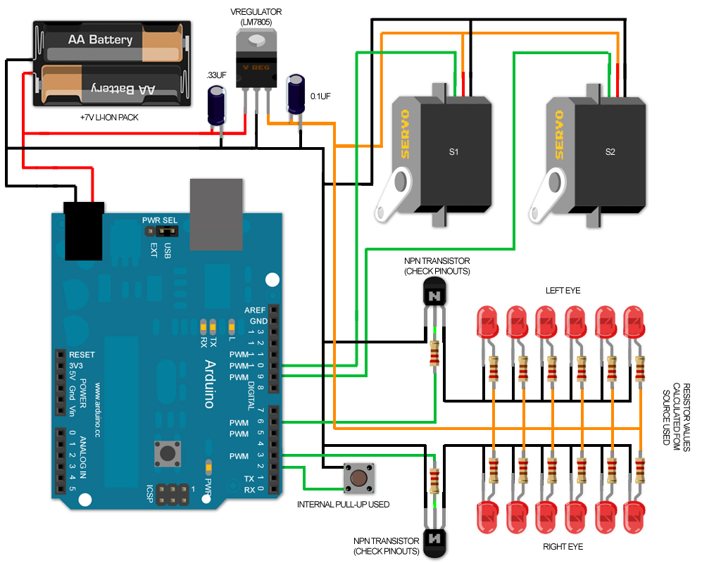
Hopefully this will clear up confusion, and offer people a FREE alternative to other justtaking the free work posted and making a profit from it.
Any questions, just ask. (I also suggest reading through the whole other thread for completensss and understanding)")
1.) decrease confusion
2.) keep posts organized, in order
3.) hopefully help others spot people making money off what was freely giving for the community here
I am posting my approach (which I'm fairly certain people have taken and made 'products' for sale from) on how to add some electronics to your Iron Man buckets.. to get a motorized face plate and led (blinking) eyes..
The original post is located here:
http://www.therpf.com/showthread.php?t=170853
(I would suggest reading it regardless, and MUCH information has been provided to help trouble shoot other members with their issues)
* Take note of member: "memebr's" post over there as well as it is solid info (with a slight variation on my wiring and code for his wiring and code)
Key notes to take with you on this adventure:
1.) Servos shoud NOT be powered (driven) by your Arduino.. it may be 'ok' to temporarily connect the servo to your Arduino (with no load, nothing attached to the servo).. but generally they need more voltage and more current than the Arduino pin can provide.. and can blow your Arduino
2.) It is best/better to power your servo's separately, and connect the GND wires together for everything,
3.) I suggest using a +7.v Li-Ion pack with some sort of voltage regulation for your servos (and Arduino board if needed)
4.) Not connecting ground wires together may result in odd behavior and/or jitter in your servos.
5.) An Arduino pin is +5v tolerant and can only provide (roughly) 20-40mA... so enough to light up 1 or 2 small accent leds (not high powered ones)
6.) Your key components (eye leds, Arduino, servos) all take different voltage (have different power needs).. keep this in mind while you design, buy your parts.
https://www.youtube.com/watch?feature=player_detailpage&v=GSzVs7_aW-Y
* Arduino usually has vRegulator on-board (depending what variant you have/use) or needs a REGULATED +5v source (not more or you'll blow it)
* Servos (please read data sheet on your particular model).. most I have seen require about +6v (some +4.8-+6).. so you need to ensure you are not giving them more
* Your led eyes is a tricky and can be set up several ways..but most leds (depends on color too) need (roughly) +2.0v (reds) to +3.3v (blues, greens..etc)..
if wired up in parallel, they require more current (in total).. if wired up in series (you require less current, and can get closer to the voltage of the battery source, and not waste as much excess voltage as heat), so depending how it is configured/wired.. you'll need a +3.3v regulator or a maybe a +6v regulator..etc..
Read: http://www.therpf.com/showthread.php?t=170853&p=2729601&viewfull=1#post2729601
Link to the eye pcb's I made:
http://www.therpf.com/showthread.php?t=170853&p=2648856&viewfull=1#post2648856
Link to calculate the resistors needed in your personal set up:
http://www.therpf.com/showthread.php?t=170853&p=2650741&viewfull=1#post2650741
Random Link to sound FX: (if applicable to your project, a bit outside the scope of this tutorial though)
http://www.therpf.com/showthread.php?t=170853&p=2650741&viewfull=1#post2650741
http://www.therpf.com/showthread.php?t=170853&p=2662440&viewfull=1#post2662440
Bring this to the next level:
* You can add audio
* You can use other ways to trigger the faceplate (bluetooh, IR, accelerometer..etc) easily added in the base code below
Example vids:
http://youtu.be/VzPivAzSb5M
My personal (final) video: (servo, lights & sounds)
http://youtu.be/cTXt8l2XH-Q
*using a 'custom' Arduino board I made (it has built-in Waveshield/microSd..etc all on-board).. roughly same size of a Nano
*plays audio (.wav file from SD card)
ref pic: http://dmstudios.net/misc/scab_assembly/flash_board.jpg
First version of code posted: (eye blink code only)
Code:
// IronMan Helmet: eye blink sequence_v1.0
// created by: xl97


// led control pins (need to be PWM enabled pins for fading)
const int leftEye =  6;  // the number of the left eye/pcb LEDs
const int rightEye =  3;  // the number of the right eye/pcb LEDs

/* we always wait a bit between updates of the display */
unsigned long delaytime = 1;
unsigned long fadespeed = 500;
unsigned long blinkspeed = 100;
unsigned long currentPWM = 0;

#define S_IDLE 1
#define S_LEDON 2
#define S_WAITON 3
#define S_LEDOFF 4
#define S_WAITOFF 5
#define S_INITON 6
#define S_INITWAIT 7
#define S_BLINKON 8


//FSM init vars
static int state = S_IDLE; // initial state is 1, the "idle" state.
static unsigned long lastTime;  // To store the "current" time in for delays.


void setup() {
  // Set up serial port
  Serial.begin(9600);
  Serial.print("INTIT STATE: ");
  Serial.println(state);

  //start it off
  state = S_BLINKON;
}


void loop() {
  switch(state)
  {
  case S_IDLE:
    // We don't need to do anything here, waiting for a forced state change...like button press.
    break;

  case S_BLINKON:
    //do blink routine here
    analogWrite(leftEye, 155);
    analogWrite(rightEye, 155);
    delay(blinkspeed);
    analogWrite(leftEye, 0);
    analogWrite(rightEye, 0);
    delay(blinkspeed);
    analogWrite(leftEye, 155);
    analogWrite(rightEye, 155);
    delay(blinkspeed);
    analogWrite(leftEye, 0);
    analogWrite(rightEye, 0);
    delay(10);
    currentPWM = 0;

    state = S_LEDON;
    break;

  case S_LEDON:
    Serial.println("increase........");
    analogWrite(leftEye, currentPWM);
    analogWrite(rightEye, currentPWM);
    lastTime = millis();  // Remember the current time
    state = S_WAITON;  // Move to the next state
    break;

  case S_WAITON:
    // If one second has passed, then move on to the next state.
    if(millis() > lastTime + delaytime)
    {
      if(currentPWM < 255){
        currentPWM++;
        state = S_LEDON;
      }
      else{
        Serial.println("@255 done........");
        state = S_IDLE;
        //state = S_LEDOFF; //no auto turn off.. set to idle state
      }
    }
    break;

  case S_LEDOFF:
    Serial.println("........decrease");
    lastTime = millis();  // Remember the current time
    state = S_WAITOFF;
    break;

  case S_WAITOFF:
    // If one second has passed, then go back to state 2.
    if(millis() > lastTime + delaytime)
    {
      if(currentPWM > 0){
        currentPWM--;
        state = S_LEDOFF;
      }
      else{
        state = S_LEDON;
      }
    }
    break;

  default:
    state = S_IDLE;
    break;
  }
}
Second version of code: (eye blink and servo)
*Summary:
1.) 1 x button (digital pin 2) controls both open and close operations
2.) when OPEN.. the servos will close and then trigger the led 'blink & fade in' routine
3.) when CLOSED... the leds will fade out then the servos will 'open'.
should be a very scalable and easy editable sketch so far:
Code:
// IronMan Helmet: eye blink sequence_v1.0
// created by: xl97
// Movie Props, Costumes and Scale Models | the RPF thread:
// http://www.therpf.com/f24/iron-man-m...ml#post2647126

//import servo lib
#include <Servo.h>

//servo object names
Servo myservo; // create servo object to control a servo
Servo myservo1;

const int buttonPin = 2; // the pin that the pushbutton is attached to
int buttonState = 0; // current state of the button
int lastButtonState = 0; // previous state of the button
int pos = 0; // variable to store the servo positions
int pos1 = 180;

// led control pins (need to be PWM enabled pins for fading)
const int leftEye =  6;  // the number of the left eye/pcb LEDs
const int rightEye =  3;  // the number of the right eye/pcb LEDs

unsigned long delaytime = 1;
unsigned long blinkspeed = 100;
unsigned long currentPWM = 0;
boolean isOpen = true;

#define S_IDLE 1
#define S_LEDON 2
#define S_WAITON 3
#define S_LEDOFF 4
#define S_WAITOFF 5
#define S_INITON 6
#define S_INITWAIT 7
#define S_BLINKON 8
#define S_SERVOUP 9
#define S_SERVODOWN 0


//FSM init vars
static int state = S_IDLE; // initial state is 1, the "idle" state.
static unsigned long lastTime;  // To store the "current" time in for delays.


void setup() {
  // Set up serial port
  Serial.begin(9600);
  //start it off
  //state = S_BLINKON;
  Serial.print("INTIT STATE: ");
  Serial.println(state);

  myservo.attach(9); // attaches the servo on pin 9 to the servo object
  myservo1.attach(10); // attaches the servo on pin 10 to the servo object

  pinMode(buttonPin, INPUT); // initialize the button pin as a input
  digitalWrite(buttonPin, HIGH); //use interal pull up resistors
}

void loop() {
  switch(state)
  {
  case S_IDLE:
    // We don't need to do anything here, waiting for a forced state change...like button press.
    //check mian button state
    buttonState = digitalRead(buttonPin);

    // compare buttonState to previous state
    if (buttonState != lastButtonState) {
      //if button pressed/down
      if (buttonState == LOW){
        //ie: pressed
        if(isOpen == true){
          Serial.print("CLOSING FACE PLATE: ");
          Serial.println(isOpen, DEC);
          state = S_SERVODOWN;
        }
        else{
          Serial.print("OPENING FACE PLATE: ");
          Serial.println(isOpen, DEC);
          //state = S_SERVOUP;
          state = S_LEDOFF;
        }
        isOpen = !isOpen;

      }
      else{
        //went from ON/HIGH to LOW/OFF..ie: released
        //Serial.print("RELEASE: ");
        //Serial.println(isOpen, DEC);
      }

    }
    // save the current state for next loop
    lastButtonState = buttonState;
    break;

  case S_BLINKON:
    Serial.println("init blink.........");
    //do blink routine here
    analogWrite(leftEye, 155);
    analogWrite(rightEye, 155);
    delay(blinkspeed);
    analogWrite(leftEye, 0);
    analogWrite(rightEye, 0);
    delay(10);
    /*
    analogWrite(leftEye, 155);
    analogWrite(rightEye, 155);
    delay(blinkspeed);
    analogWrite(leftEye, 0);
    analogWrite(rightEye, 0);
    delay(10);
    */
    currentPWM = 0;
    state = S_LEDON;
    break;

  case S_LEDON:
    Serial.println("increase........");
    lastTime = millis();  // Remember the current time
    analogWrite(leftEye, currentPWM);
    analogWrite(rightEye, currentPWM);
    state = S_WAITON;  // Move to the next state
    break;

  case S_WAITON:
    // If one second has passed, then move on to the next state.
    if(millis() > lastTime + delaytime)
    {
      if(currentPWM < 255){
        currentPWM += 5;
        state = S_LEDON;
      }
      else{
        Serial.println("@ 255 done........");
        state = S_IDLE;
        //state = S_LEDOFF; //no auto turn off.. set to idle state
      }
    }
    break;

  case S_LEDOFF:
    Serial.println("........decrease");
    lastTime = millis();  // Remember the current time
    analogWrite(leftEye, currentPWM);
    analogWrite(rightEye, currentPWM);
    state = S_WAITOFF;
    break;

  case S_WAITOFF:
    // If one second has passed, then move on to the next state.
    if(millis() > lastTime + delaytime)
    {
      if(currentPWM > 0){
        currentPWM -= 5;
        state = S_LEDOFF;
      }
      else{
        Serial.println("@ 0 done........");
        state = S_SERVOUP; //leds off..raise faceplate
      }
    }
    break;

  case S_SERVOUP:
    myservo.write(100);
    myservo1.write(100);
    //delay(20); //wait to trigger the led flicker.. will remove delay() use in next revision
    state = S_IDLE;
    Serial.println("servo up.........");
    break;

  case S_SERVODOWN:
    myservo.write(0);
    myservo1.write(0);
    delay(20); //wait to trigger the led flicker.. will remove delay() use in next revision
    state = S_BLINKON;
    Serial.println("servo down.........");
    break;

  default:
    state = S_IDLE;
    break;
  }
}
3rd version of code:
* here is an updated version...
where you can easily control the 'wait' between when you call/start the eye flicker/fade in, after the face plate servo starts to bring it down.. (easy to time your own servo/wait...etc)
Code:
// IronMan Helmet: eye blink sequence_v1.0
// created by: xl97


//import servo lib
#include <Servo.h>

//servo object names
Servo myservo; // create servo object to control a servo
Servo myservo1;

const int buttonPin = 2; // the pin that the pushbutton is attached to
int buttonState = 0; // current state of the button
int lastButtonState = 0; // previous state of the button


// led control pins (need to be PWM enabled pins for fading)
const int leftEye =  6;  // the number of the left eye/pcb LEDs
const int rightEye =  3;  // the number of the right eye/pcb LEDs

unsigned long fadeDelay = .5; //speed of the eye 'fade'
unsigned long callDelay = 700; //length to wait to start eye flicker after face plate comes down
unsigned long blinkSpeed = 100; //delay between init blink on/off
unsigned long currentPWM = 0;
boolean isOpen = true;

#define S_IDLE 1
#define S_LEDON 2
#define S_WAITON 3
#define S_LEDOFF 4
#define S_WAITOFF 5
#define S_INITON 6
#define S_INITWAIT 7
#define S_BLINKON 8
#define S_SERVOUP 9
#define S_SERVODOWN 0
#define S_SERVOWAIT 10


//FSM init vars
static int state = S_IDLE; // initial state is 1, the "idle" state.
static unsigned long lastTime;  // To store the "current" time in for delays.


void setup() {
  // Set up serial port
  Serial.begin(9600);
  //start it off
  //state = S_BLINKON;
  Serial.print("INTIT STATE: ");
  Serial.println(state);

  myservo.attach(9); // attaches the servo on pin 9 to the servo object
  myservo1.attach(10); // attaches the servo on pin 10 to the servo object

  pinMode(buttonPin, INPUT); // initialize the button pin as a input
  digitalWrite(buttonPin, HIGH); //use interal pull up resistors
}

void loop() {
  switch(state)
  {
  case S_IDLE:
    // We don't need to do anything here, waiting for a forced state change...like button press.
    //check mian button state
    buttonState = digitalRead(buttonPin);

    // compare buttonState to previous state
    if (buttonState != lastButtonState) {
      //if button pressed/down
      if (buttonState == LOW){
        //ie: pressed
        if(isOpen == true){
          Serial.print("CLOSING FACE PLATE: ");
          Serial.println(isOpen, DEC);
          state = S_SERVODOWN;
        }
        else{
          Serial.print("OPENING FACE PLATE: ");
          Serial.println(isOpen, DEC);
          //state = S_SERVOUP;
          state = S_LEDOFF;
        }
        isOpen = !isOpen;
      }
      else{
        //went from ON/HIGH to LOW/OFF..ie: released
        //Serial.print("RELEASE: ");
        //Serial.println(isOpen, DEC);
      }
    }
    // save the current state for next loop
    lastButtonState = buttonState;
    break;

  case S_BLINKON:
    Serial.println("init blink.........");
    //do blink routine here
    //one blink
    analogWrite(leftEye, 155);
    analogWrite(rightEye, 155);
    delay(blinkSpeed);
    analogWrite(leftEye, 0);
    analogWrite(rightEye, 0);
    delay(10);
    //two blinks
    /*
    analogWrite(leftEye, 155);
     analogWrite(rightEye, 155);
     delay(blinkSpeed);
     analogWrite(leftEye, 0);
     analogWrite(rightEye, 0);
     delay(10);
     */
    state = S_LEDON;
    break;

  case S_LEDON:
    Serial.println("increase........");
    lastTime = millis();  // Remember the current time
    analogWrite(leftEye, currentPWM);
    analogWrite(rightEye, currentPWM);
    state = S_WAITON;  // Move to the next state
    break;

  case S_WAITON:
    // If one second has passed, then move on to the next state.
    if(millis() > (lastTime + fadeDelay)){
      if(currentPWM < 255){
        currentPWM += 5;
        state = S_LEDON;
      }
      else{
        Serial.println("@ 255 done........");
        state = S_IDLE;
        //state = S_LEDOFF; //no auto turn off.. set to idle state
      }
    }
    break;

  case S_LEDOFF:
    Serial.println("........decrease");
    lastTime = millis();  // Remember the current time
    analogWrite(leftEye, currentPWM);
    analogWrite(rightEye, currentPWM);
    state = S_WAITOFF;
    break;

  case S_WAITOFF:
    // If one second has passed, then move on to the next state.
    if(millis() > (lastTime + fadeDelay)){
      if(currentPWM > 0){  //change 0 to higher number to init face 'up' function sooner.
        currentPWM -= 5;
        state = S_LEDOFF;
      }
      else{
        Serial.println("@ 0 done........");
        state = S_SERVOUP; //leds off..raise faceplate
      }
    }
    break;

  case S_SERVOUP:
    Serial.println("servo up.........");
    myservo.write(100);
    myservo1.write(100);
    state = S_IDLE;
    break;

  case S_SERVODOWN:
    lastTime = millis();  // Remember the current time
    Serial.println("servo down.........");
    myservo.write(0);
    myservo1.write(0);
    state = S_SERVOWAIT;
    break;

  case S_SERVOWAIT:
    // If enough time has passed, call the eye flicker routine
    if(millis() > (lastTime + callDelay)){
      Serial.println("start eye flicker routine");
      state = S_BLINKON;
    }
    else{
      Serial.println("waiting........");
    }
    break;

  default:
    state = S_IDLE;
    break;
  }
}
Wiring:
Hopefully this will clear up confusion, and offer people a FREE alternative to other justtaking the free work posted and making a profit from it.
Any questions, just ask. (I also suggest reading through the whole other thread for completensss and understanding)
