Trigun: Frank Marlon Special Revolver

Tatsutetsu

Member
Here’s my build log for a scratch built Frank Marlon Special revolver, a signature firearm from the Trigun universe I’ve wanted to make for a while now due to its distinct look and its significance to the story in the episode it featured in


Trigunartbook26_zpsa501c309.jpg
Trigunartbook10_zpse542b7c9.jpg


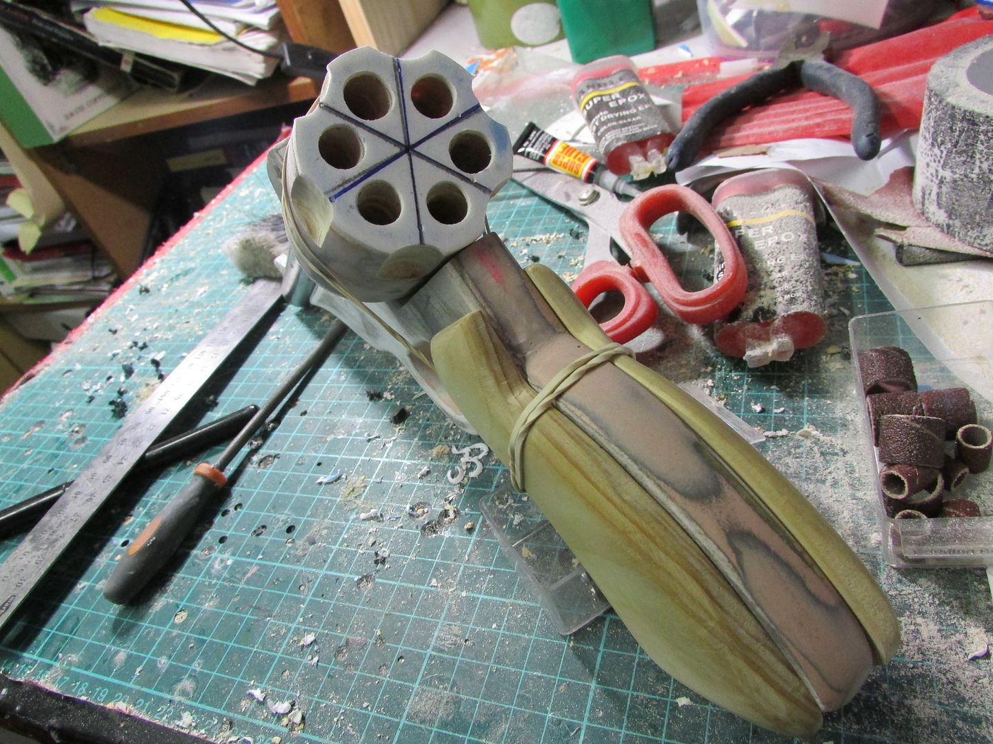
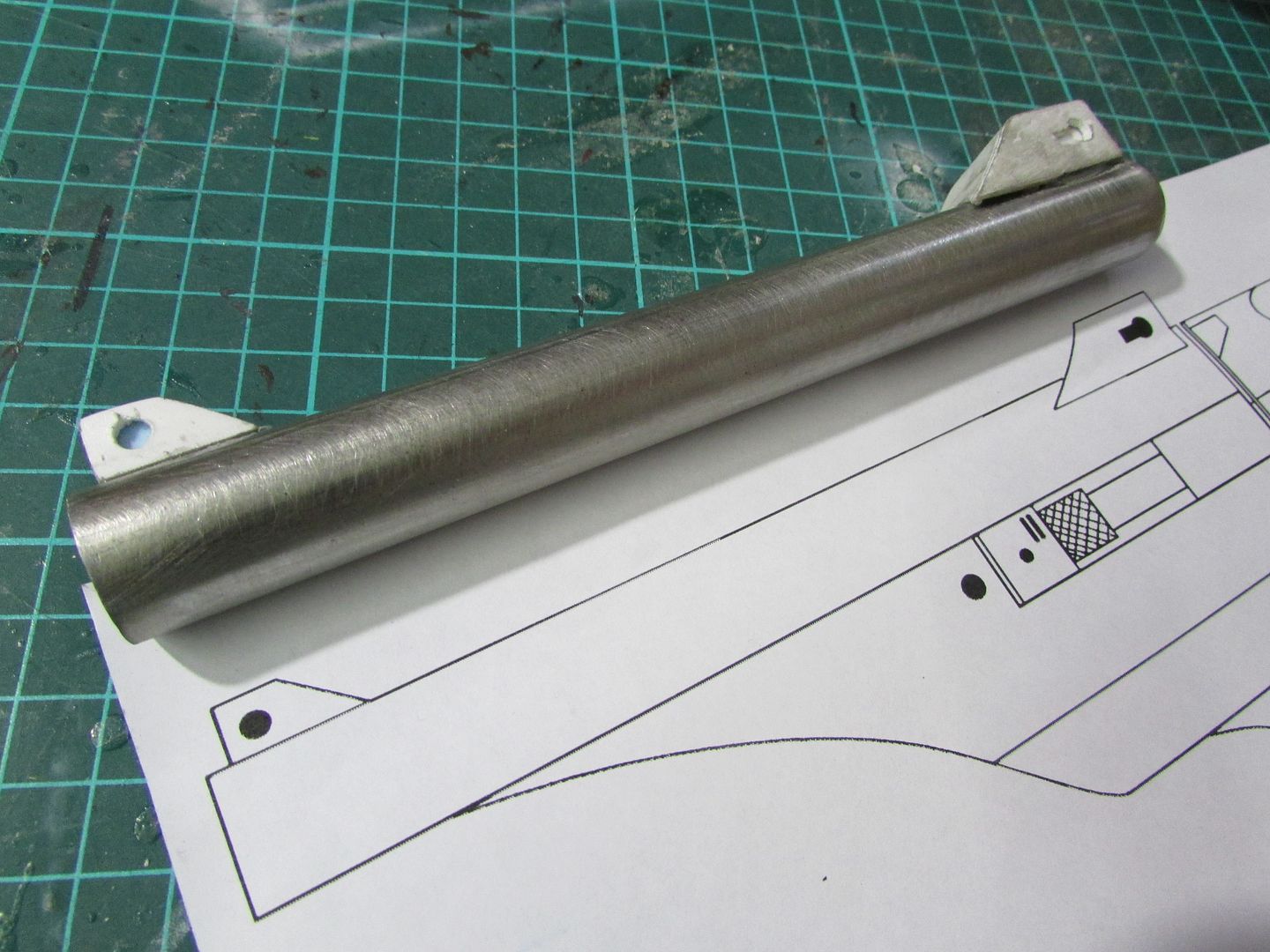
To begin with in terms of scaling, using what glimpses of the gun that the episode provided I decided to base off the dimensions of the revolver with reference to my own thumb as the length of the cylinder and then scaled all related parts to that baseline length and the reference from the concept artbook, resulting in a set of plans I could then use for the build.


frank_zps25fbc5a3.png


IMG_3611_zps803bdc52.jpg


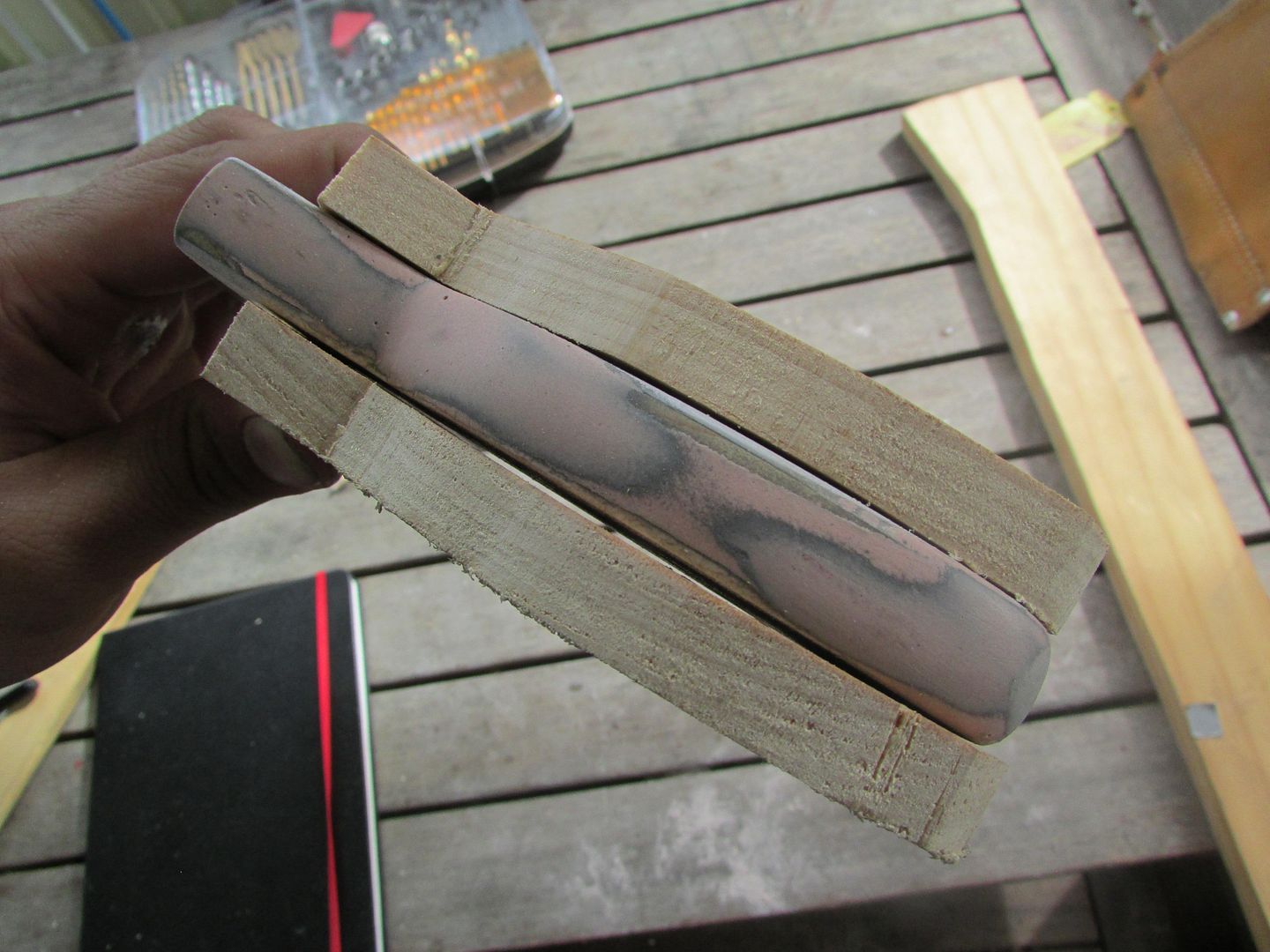
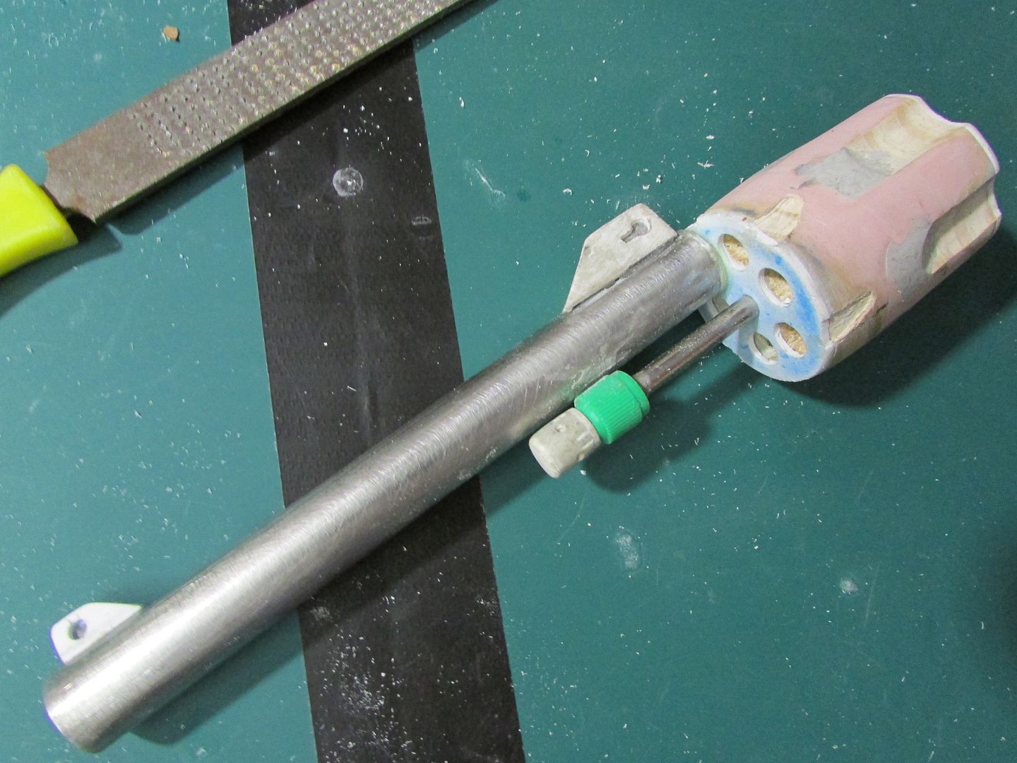
Starting off with the barrel of the gun, I found an old rusted steel tube from what was once a clothes dryer, whose diameter (18mm) suited the scaled dimensions of the plans.So I cut it to length using a hacksaw and roughened the cut edge using some 80 grit sandpaper to eliminate the risk of cutting oneself.


IMG_3614_zps9688874d.jpg


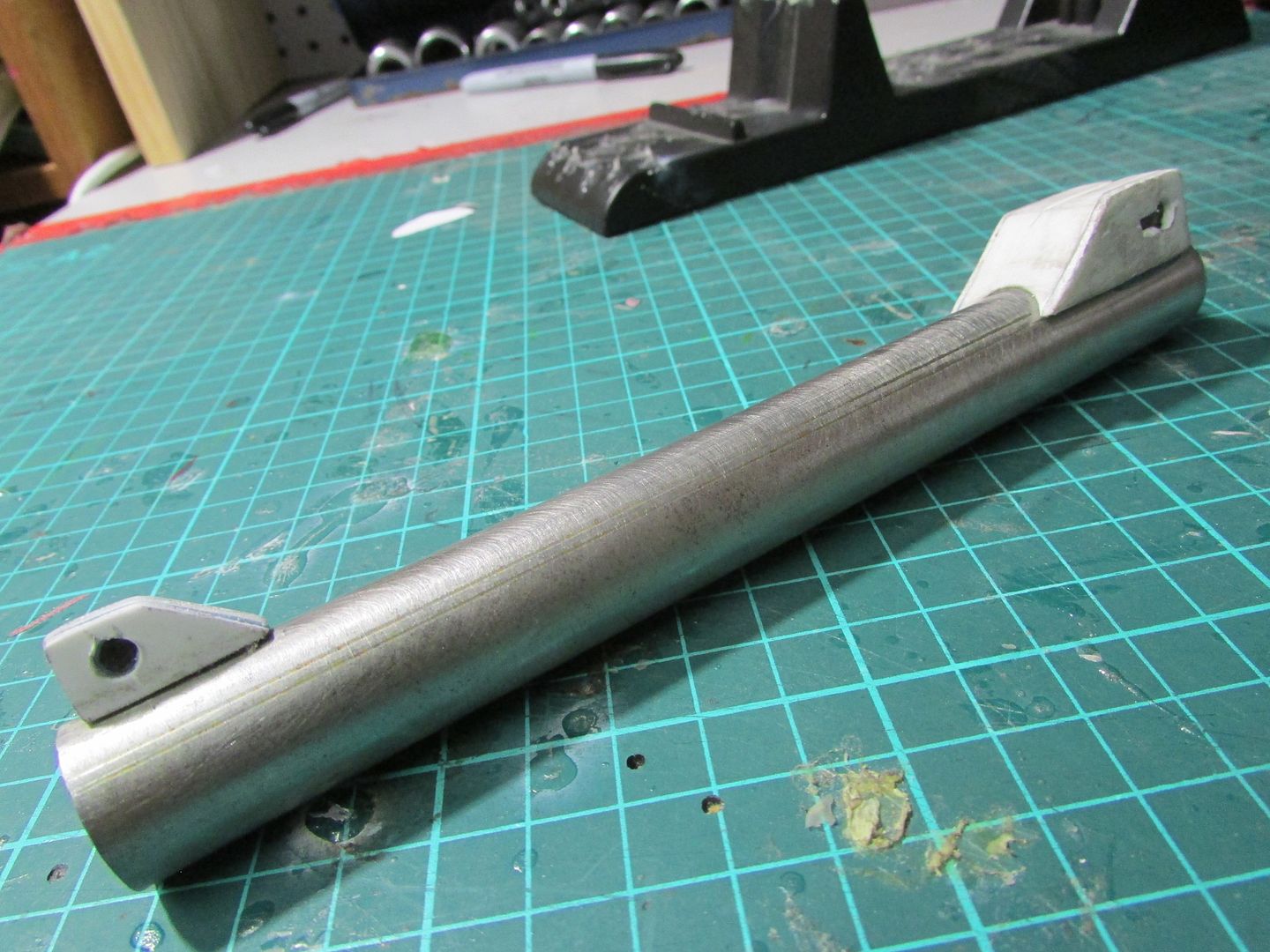
To clean off the rust build up I used some 240 grit sandpaper to get it back to its pristine state, and at 175mm in length the barrel will do just fine.

IMG_3615_zps0ffc1cab.jpg


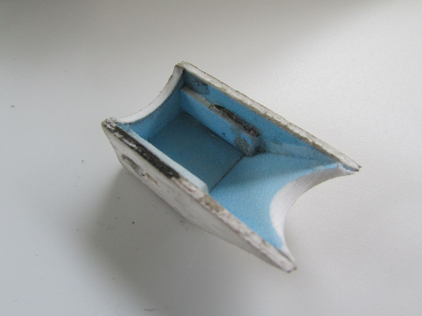
Moving on to making the sights on the barrel I decided to use some plastic sheeting, and starting with the side pieces and gradually built the component so it would be able to eventually sit on the barrel and detailing the pieces using a drill and a hobby knife kit.

IMG_3624_zpsf5067d0a.jpg


IMG_3629_zps9fbf04f2.jpg


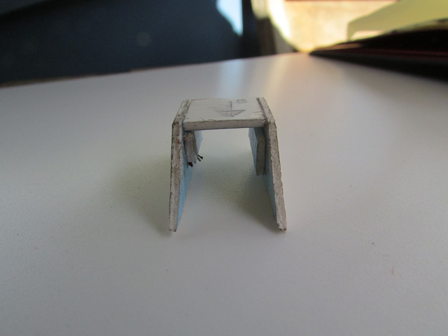
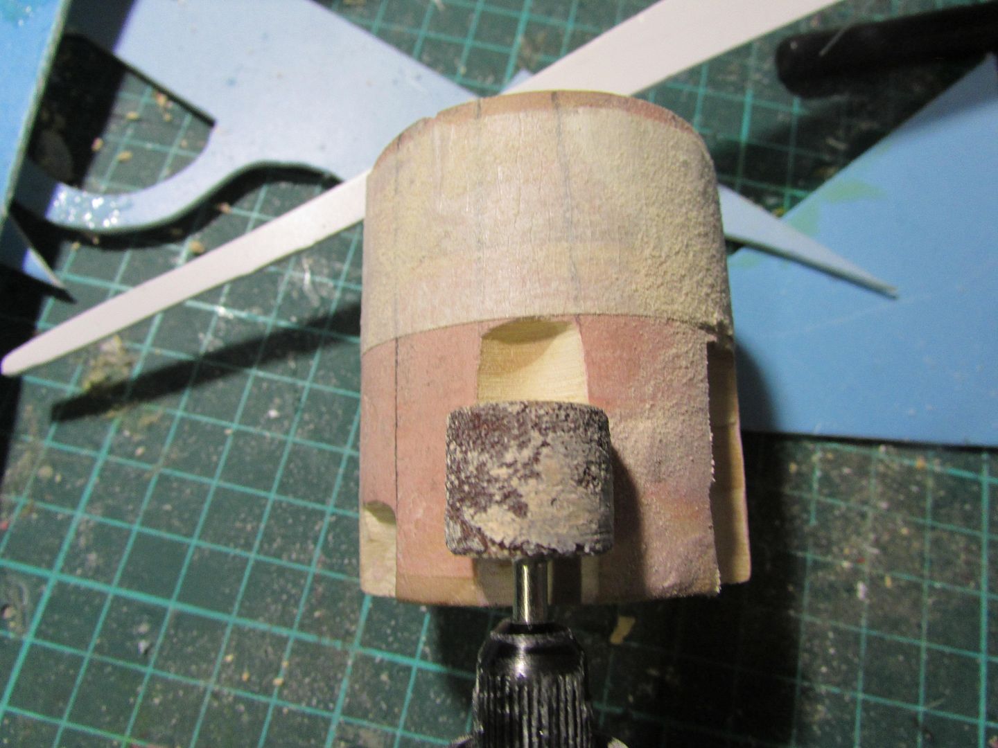
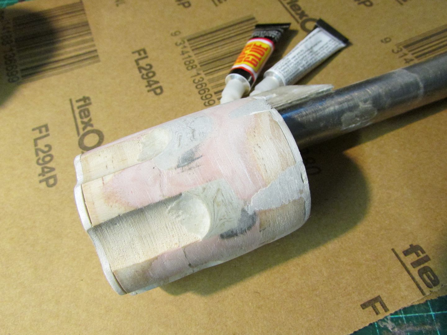
However when it finally came to the front and back panels of the sight, to be able to accommodate the curvature of the barrel so it would maintain alignment and sit flush I used a rotary tool with a grinding drum bit and incrementally widdled away the edges until it sat flush with the barrel but still maintained alignment.

IMG_3640_zps88487590.jpg


IMG_3641_zps838a9827.jpg


IMG_3635_zps066b6c84.jpg


IMG_3642_zpsa67f9473.jpg


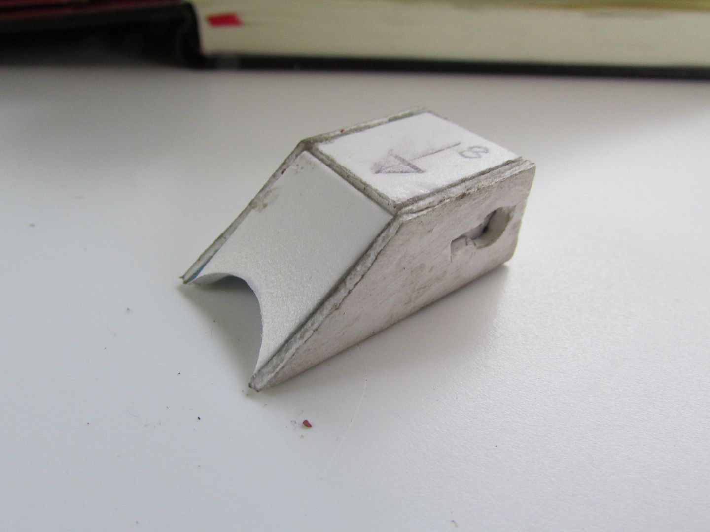
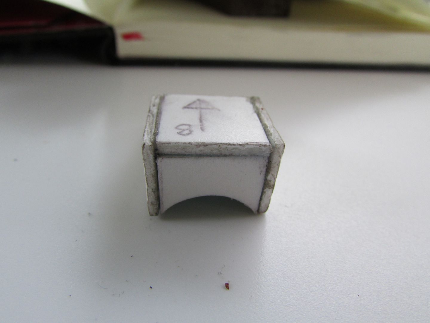
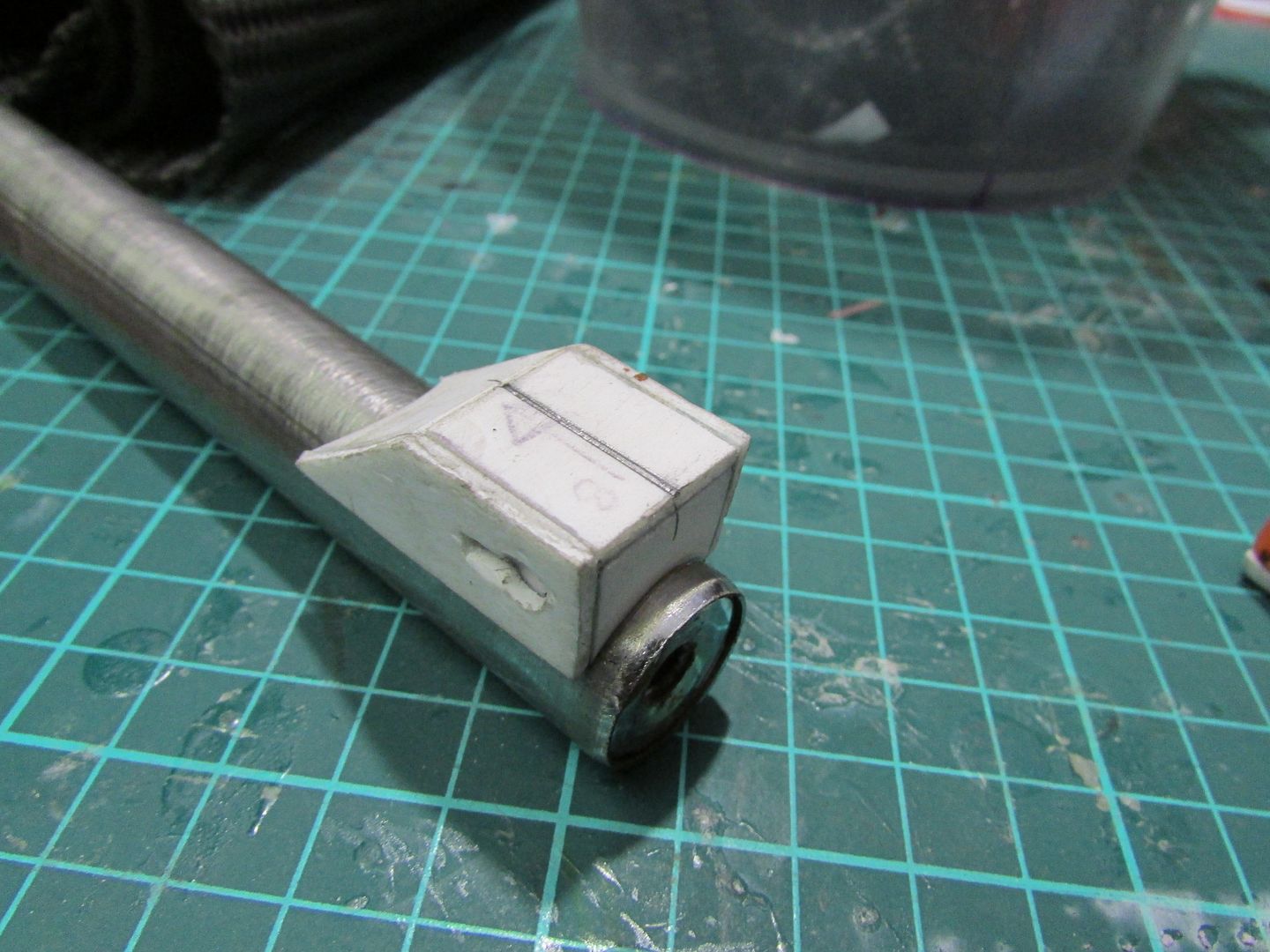
With a nice sit I then used some epoxy adhesive to attach it to the barrel proper and repeated a similar process for the sight at the end of the barrel.

IMG_3647_zpsd5f4208d.jpg


IMG_36751_zps35393772.jpg

 
Last edited:
With the rough shape cut out, it then came the first pass of Bondo and sanding, started with 80 grit to remove most of the bulk material and working my way up through 180 to 240 to refine the profile of the frame. I SHould mention I glued on to both sides some plastic cutouts to act as a guide to know when to stop sanding till.

IMG_3690_zpsfcf0379d.jpg
IMG_3691_zpsf264ee73.jpg
IMG_3692_zpse3b3b62c.jpg


For the second pass I gave the frame a quick once over with primer to highlight any defects I missed and to fill in at the same time. and repeated the whole process of sanding once more.

IMG_3694_zps8cbf7f5c.jpg


Occasionally when I’m doing this process I find small patches of defects in awkward to fill places like this especially inside the trigger guard where it would be difficult to smear bondo there effectively so I like to use Selley’s Knead it which is an epoxy polymer compound that hardens in a very short tie and can be sanded just as easy as the bondo.


IMG_3696_zps2bc21308.jpg


IMG_3699_zpsd070c826.jpg
 
I Cut out the revovler grips out of 12mm thick pine today, using the handle section of the frame as a template.

IMG_3707_zps85bfca86.jpg


IMG_3709_zps3294720d.jpg


Making do with what tools I have, I had my portable belt sander fixed in a vice and fed the wooden grips into the belt to gradually bevelling the edges until the grips when attached to the frame felt ergonomic in my hands.

IMG_3712_zpsbe2ac83f.jpg


IMG_3713_zps5361cc31.jpg


Just enough to get a rough profile that I need, I then refined the shapes using sandpaper until I got a really nice curve surface.

IMG_3715_zps34f895ee.jpg


Test fitting everything I have so far its starting to look more and more like the revolver.

IMG_3716_zpsd0e08374.jpg


IMG_3718_zps6b375af8.jpg


IMG_3721_zps5834c0f5.jpg
 
Nice looking progress! Only thing that bothers me is that the part where the barrel meets the frame, around the ejector rod, should be thinner than around the grip and triggerguard. The overall shape reminds me of the Van Helsing revolvers.


_A
 
Nice looking progress! Only thing that bothers me is that the part where the barrel meets the frame, around the ejector rod, should be thinner than around the grip and triggerguard. The overall shape reminds me of the Van Helsing revolvers.


_A

Thank you

Are you talking about the front fin part or the rectagular gap where the ejector rod will slot into?

I can definitely see that in terms of shape

11382_2.jpg


but I'm still trying to to discern what real world gun influence the designers of the show decided to use used in their illustrations at the moment I’m guessing some variant of Remington revolver especially in terms of the profile made from the loading lever.

FHG-1435-Product.jpg
 
Yeah, the fin seems to continue in uniform thickness from the frontmost part all the way back to the cylider, and looks to me to be thinner than the frame below it.
crappy pic is crappy.jpg
The area between the red lines is what I'm talking about, and the other bracket-like lines representing what it would look like from the front. Sorry about the poor picture.

The Remington looks very alike.

_A
 
Yeah, the fin seems to continue in uniform thickness from the frontmost part all the way back to the cylider, and looks to me to be thinner than the frame below it.
View attachment 340699
The area between the red lines is what I'm talking about, and the other bracket-like lines representing what it would look like from the front. Sorry about the poor picture.

The Remington looks very alike.

_A

no no its alright, I see what you mean, but a thin plate like web or something with a bit of thickness to it? it's a bit ambiguous
 
Last edited:
no no its alright, I see what you mean, but a thin plate like web or something with a bit of thickness to it? it's a bit ambiguous

Yeah, it's a little hard to explain with words. Regardless, what you got going looks amazing!

_A
 
Making drawings for the cylinder of the revolver I’ve noticed for what ever reason the designers of the show have drawn the cylinder in backwards which adds confusion as to how this revolver actually functions
 
Did a bit of work on the cylinder today, I used a 54mm diameter hole saw and cut out three 19mm thick sections that would eventually make up the base stock of the cylinder, which I then sandwiched together using wood glue giving me 57mm length overall.

IMG_3725_zps0dcd7f30.jpg


From there did an initial cleanup with sandpaper when the glue had dried and I found that some of the seams between each slices were still exposed, so a thin covering of bondo and subsequent sanding and smoothing was performed.

IMG_3726_zps28e7b3aa.jpg


To produce the bullet chambers, I used a template and a centre punch to make the initial indent to which I then progressively drilled holes starting from smaller sizes until I reached a final diameter of 9mm.

IMG_3729_zps01483989.jpg


IMG_3730_zps3d1b50bf.jpg


IMG_3731_zps19f05b88.jpg
 
Carving the slots on the side of the revolver using a rotary tool is going well, however the inside faces of the barrel chambers are looking pretty ugly, not sure how to go about cleaning those up other than starting over using MDF
 
With a decent sized cylinder shaped I've gone about cuting out the slot on the side of the cylinder using a rotary tool and a bit of masking tape to act as a guide.

IMG_3736_zps053d6608.jpg


So far the shape is looking pretty good now I need to clean up more of the edges with light sanding.

IMG_3739_zps2c82c6aa.jpg
 
To help with the refinement of the cylinder groove shapes, I’ve attached some end faces so I have a reference to better match the contours. They also make the exposed faces look decent and hide some of the defects underneath.

IMG_3749_zps64eed88c.jpg


I also glued the barrel to the cylinder and gave the makeshift ejector rod a test fit and its looking more revolver like overall, however as you can see the recessed grooves at the front end aren’t looking to flash, since I'm losing alot of the shape using these small linoleum chisels .

IMG_38061_zps38882a46.jpg


Any suggestions anyone can recommend as to how to go about making these slots?

groove.jpg
 
They look almost like index or "safety" slots; index slots are what lock the cylinder in the proper alignment. Safety slots are notched on some old style revolvers that are in-between each bullet hole; this lets you put the hammer down into the notch instead of having it rest on a loaded chamber.

Neither of which would really be in the proper place on this gun :lol (although still very cool looking)


The drawing you're using almost makes it look like the notches/slots are cut at an angle, like I/ ("front on" view, as if you're looking at the cylinder's round face) and tapered in depth from "deep" at the cylinder front, to "shallow" further back. Hope that makes sense.

Whatever shape you end of making the notches, I'd personally use small files to cut them in.


Here's a few photo links shamelessly borrowed from Google that show both kinds of slots;

http://truthaboutguns-zippykid.netdna-ssl.com/wp-content/uploads/2014/04/9.jpg

http://upload.wikimedia.org/wikipedia/commons/4/45/New_model_Army_IMG_3544.jpg

http://collectorebooks.com/jamesauction/colt-revolver/image4/32275x4.jpg

http://www.dixiegunworks.com/images/CY0501.JPG

http://media.midwayusa.com/productimages/880x660/Primary/857/857132.jpg
 
Neither of which would really be in the proper place on this gun :lol (although still very cool looking)

I completely agree, I noticed that going into the build where the shows mechanical designer just decided to flip the cylinder around for purely aesthetic reasons :D

I'll re-bondo the poorly done notches and have another pass eventually when I get the opportunity.
 
Revolver slots redux.

Not being content with the revolver slots I had done prior I decided to start over using some plumbers epoxy to fill in most of the gaps and sanded it down to get back to the base cylinder.


IMG_4222_zps703cbc20.jpg


In conjunction with this I also used a trick I read somewhere of using baking powder as a catalyst for superglue (cyanoacrylate), whereby the baking powder reacts almost instantaneously with the superglue to form a solid that easily sands and cracks like acrylic or glass

Filling in these minor cracks instantly without having to wait for the cure time like with bondo or other filler means.

IMG_4224_zpsa30f2a26.jpg


Just layer the area to be filled with the baking powder and a few drops of superglue and watch the science happen

IMG_4225_zps143d4208.jpg

IMG_4226_zpsb548b4eb.jpg


With the cylinder back at step one, this time around taking my time and using a new set of jeweller files I picked up I’m seeing nicer results.

IMG_4230_zpsa70efc6b.jpg
 
Last edited:
Back
Top