VincePopcorn
New Member
I think Arky's UI and animation is beautiful.
I have no experience in coding animation though, but do have experience using After Effects and was able to knock up a few TNG style animations.
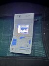
Here I've replaced the main graphics part of Arky's code with one that simply displays an animated GIF. It plays pretty well, and the memory on the Pico seems to have space for around 20 seconds or so of animation. It's not quite as crisp or smooth as the programmically animated sprites, but does allow for some more detailed animation design.
I've also updated the sound slightly. I found a really nice Tricorder sample (actually on the Generation soundtrack, link searchable on youtube), which I've EQ-ed a bit, to make the high pitch part stand out from the low frequency warble. I prefer it.
Video example attached.
I have no experience in coding animation though, but do have experience using After Effects and was able to knock up a few TNG style animations.
Here I've replaced the main graphics part of Arky's code with one that simply displays an animated GIF. It plays pretty well, and the memory on the Pico seems to have space for around 20 seconds or so of animation. It's not quite as crisp or smooth as the programmically animated sprites, but does allow for some more detailed animation design.
I've also updated the sound slightly. I found a really nice Tricorder sample (actually on the Generation soundtrack, link searchable on youtube), which I've EQ-ed a bit, to make the high pitch part stand out from the low frequency warble. I prefer it.
Video example attached.