Robajob
New Member
As proposed in my first post Matt Smith Tardis http://www.therpf.com/showthread.php?t=276113 and subsequently requested by members I am undertaking a build thread for this scratch built project.
I will post this in complete sections so as not to be too longwinded/boring and will try to post 1 or 2 a week, time allowing.
Firstly let me start off by stating the initial build was inspired, affected and requested by my son, who I would definitely class as a Whovian even at his tender age. So how could one refuse the request of a small boy that has requested “My very own Tardis”!
With such a keen interest in anything Doctor Who, I have found that encouraging his fanaticism is a way of leading him to other interesting learning discoveries and opens that wonderful world of imagination.
So with his request being the initial inspiration/motivation, I started to do some research, designing and general digging around to see what I could eventually use to make this request become a reality on a budget.
The first thing I came across was the fantastic resource of Google maps, which I am sure that most Dr Who fans will be aware that if you visit the Police Box at Earl’s Court you can actually go inside theTardis and within certain limitations have a good look around the whole Tardis.
Research done! With this resource in hand I felt I had a very good head start on getting to grips with the project, so I started trying to get a sense of scale and overall size, and soon realised this was going to be big!
It was at this point that I came across a brilliant site called AFT (Action FigureTheatre), which has some excellent sets that you can download, print and put together to use with your action figures.
A vast amount of the work already done for you, what more could you ask for.
Unfortunately that was when the initial request changed, it wasn’t just” My very own Tardis” my son wanted, it had to have “moving parts and lights” just like his shop bought David Tennant Tardis.
OK, that could be do-able, the next request was lightweight enough to move around, or more precisely ”So I can take it to Grandma’s”, ok that shouldn’t be too much of a problem either and the last request, “It has to look like the real thing”, ok that’s a given, but out the window went any artistic license and compromise.
So I set about using the AFT Tardis set as a base of construction from which to resize, redraw, increase the accuracy and alter the construction from card stock to something lightweight but more substantial in order for it to actually become structural.
But for now, some pictures showing the initial setup and construction of the Main Base and Struts which would form the basic skeleton from which to build the remainder.

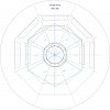
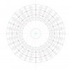
Basic Floor Plan Design drawn up using publisher with elements resized, redrawn for scale and accuracy.

Drawing of the Strut Side Elevation scaled to account for figure size, doors and relevant to reference material.

The Main Base was cut from 6mm plywood, using the Basic Floor Plan Design drawing above.
Struts were routed out by hand from 12mm MDF using the Side Elevation as a template.

Landing Floor Panels cut from 6mm ply using the Basic Floor Plan Design and in the picture below installed temporarily.


The obligatory check for scale, or rather “The Doctor surveys the construction progress to date”.

Check done and passed by the Doctor, the installation of the structural support for the landing was installed using 2mm styrene.

And the remainder of the supports installed.

Strut painting undertaken using acrylic paints, upon closer inspection you may notice that there are actually 3 colours sponge applied over the blue basecoat to give texture and depth to try and match the original paintwork.

Main Base and Landing Panels were base coated with acrylics.
So as far as stage 1 Main Base and Struts goes, that all for now folks!


View attachment 1. Tardis Main Base + Struts.jpg


I will post this in complete sections so as not to be too longwinded/boring and will try to post 1 or 2 a week, time allowing.
Firstly let me start off by stating the initial build was inspired, affected and requested by my son, who I would definitely class as a Whovian even at his tender age. So how could one refuse the request of a small boy that has requested “My very own Tardis”!
With such a keen interest in anything Doctor Who, I have found that encouraging his fanaticism is a way of leading him to other interesting learning discoveries and opens that wonderful world of imagination.
So with his request being the initial inspiration/motivation, I started to do some research, designing and general digging around to see what I could eventually use to make this request become a reality on a budget.
The first thing I came across was the fantastic resource of Google maps, which I am sure that most Dr Who fans will be aware that if you visit the Police Box at Earl’s Court you can actually go inside theTardis and within certain limitations have a good look around the whole Tardis.
Research done! With this resource in hand I felt I had a very good head start on getting to grips with the project, so I started trying to get a sense of scale and overall size, and soon realised this was going to be big!
It was at this point that I came across a brilliant site called AFT (Action FigureTheatre), which has some excellent sets that you can download, print and put together to use with your action figures.
A vast amount of the work already done for you, what more could you ask for.
Unfortunately that was when the initial request changed, it wasn’t just” My very own Tardis” my son wanted, it had to have “moving parts and lights” just like his shop bought David Tennant Tardis.
OK, that could be do-able, the next request was lightweight enough to move around, or more precisely ”So I can take it to Grandma’s”, ok that shouldn’t be too much of a problem either and the last request, “It has to look like the real thing”, ok that’s a given, but out the window went any artistic license and compromise.
So I set about using the AFT Tardis set as a base of construction from which to resize, redraw, increase the accuracy and alter the construction from card stock to something lightweight but more substantial in order for it to actually become structural.
But for now, some pictures showing the initial setup and construction of the Main Base and Struts which would form the basic skeleton from which to build the remainder.

Basic Floor Plan Design drawn up using publisher with elements resized, redrawn for scale and accuracy.

Drawing of the Strut Side Elevation scaled to account for figure size, doors and relevant to reference material.

The Main Base was cut from 6mm plywood, using the Basic Floor Plan Design drawing above.
Struts were routed out by hand from 12mm MDF using the Side Elevation as a template.

Landing Floor Panels cut from 6mm ply using the Basic Floor Plan Design and in the picture below installed temporarily.


The obligatory check for scale, or rather “The Doctor surveys the construction progress to date”.

Check done and passed by the Doctor, the installation of the structural support for the landing was installed using 2mm styrene.

And the remainder of the supports installed.

Strut painting undertaken using acrylic paints, upon closer inspection you may notice that there are actually 3 colours sponge applied over the blue basecoat to give texture and depth to try and match the original paintwork.

Main Base and Landing Panels were base coated with acrylics.
So as far as stage 1 Main Base and Struts goes, that all for now folks!
View attachment 1. Tardis Main Base + Struts.jpg
Last edited by a moderator:


