You are using an out of date browser. It may not display this or other websites correctly.
You should upgrade or use an alternative browser.
You should upgrade or use an alternative browser.
S-foil deployment mechanism upgrade - 1:48 MPC X-wing
- Thread starter Hagoth
- Start date


rbeach84
Sr Member
Cool design! What is your production concept? Will you be using the same basic mechanism (scaled as needed) combined with unique adapter parts such as end plates designed for each application... or will each application be slightly different with fully integrated components? Because it seems there are two separate integration boundaries ('interfaces'), one being the mechanism to the mount and the other being the mount to the model. Given the mechanism provides exactly the same function regardless of scaling (assuming the included range runs from the AMT kit - not snap-tite - to the Hasbro 'toy'), it follows the design would remain unchanged except for the specific kit interfaces - presenting an opportunity to simplify the design problem by separating the two...
Regards, Robert
Regards, Robert
Last edited:
Hagoth
Sr Member
Thanks rbeach84. I had not planned on scaling up the manual drive option as it was to be for my original MPC model only. If there is enough interest ....
You are correct that the interfaces with the different scales requires some tweaking both in mounting the mechanism and interfacing with the back. The basic concept stays the same regardless of the scale so the functionality does not change from scale to scale. The only one that will have to change is a potential design for a 1:72 scale which was not originally planned. It will not have a drive shaft and will work by opening the wings directly. Magnets will keep the wings either open or closed as it will no longer have the self locking feature but it will not wobble and the wings will be synchronized.
What I have discovered (not unexpected) is that not all models even scale proportionately. For example the 1:35 Pro Shop has less room behind the mechanism than the 1:48 MPC. Hardly enough room to do a manual drive without some major revisions unless you can grab and turn something only 4 mm long. Also when scaled up to handle the wing thickness it is too long for the wing box so the bearings need to be thinner. Functionality still stays the same just proportioned a little differently. At any rate it looks like I still have to deal with unique mounting and interfacing with each scale.
By way of a sneak update... I'm still waiting for some of the printed parts to do a complete unit but I have the clutch parts in hand and I must say they fit like a charm and perform just like the simulation. Pretty darn cool! :cool I'll post pictures of the entire unit when I have it.
You are correct that the interfaces with the different scales requires some tweaking both in mounting the mechanism and interfacing with the back. The basic concept stays the same regardless of the scale so the functionality does not change from scale to scale. The only one that will have to change is a potential design for a 1:72 scale which was not originally planned. It will not have a drive shaft and will work by opening the wings directly. Magnets will keep the wings either open or closed as it will no longer have the self locking feature but it will not wobble and the wings will be synchronized.
What I have discovered (not unexpected) is that not all models even scale proportionately. For example the 1:35 Pro Shop has less room behind the mechanism than the 1:48 MPC. Hardly enough room to do a manual drive without some major revisions unless you can grab and turn something only 4 mm long. Also when scaled up to handle the wing thickness it is too long for the wing box so the bearings need to be thinner. Functionality still stays the same just proportioned a little differently. At any rate it looks like I still have to deal with unique mounting and interfacing with each scale.
By way of a sneak update... I'm still waiting for some of the printed parts to do a complete unit but I have the clutch parts in hand and I must say they fit like a charm and perform just like the simulation.
Pretty darn cool! :cool I'll post pictures of the entire unit when I have it.rbeach84
Sr Member
RE: the short shaft clearance, what if you used a telescoping barrel sleeve to engage the shaft end? Also, what is the shaft rotation range going from open to closed (full range?) If 360, then you could incorporate the rear 'hatch' detail as the turn knob. To explain better, consider pulling the hatch (mounted on a telescoping sleeve shaft) out using the 'tank turret skirt' to pull on, then turning one rotation, then pushing it back in place. Or is this what you already have established?
Alternative is to make the hatch detail a removable cover (magnets? friction fit?), and use something like a standard Allen (or Torx) wrench to engage the shaft... this may in fact be the easiest, all purpose solution for a manual drive for all applications.
Sorry, don't mean to be 'up in your business' but rather just 'brainstorming' a bit (sounding board effect!) Hope no offense given by asking so many Q's....
Regards, Robert
Last edited:
Hagoth
Sr Member
Did you miss the video? What you described is exactly what I was trying to demonstrate there. The sliding clutch telescopes out through the back plate and engages the driver clutch mounted on the end of the drive shaft. The "hatch" or what I'm calling the servo hub is what you grab on to pull it out and turn to open the wings. It will turn between 180 - 210 degrees. Just having it pop off and using a flat head screwdriver is another option I considered but that just didn't seen to be cool enough. :lol Functional though as an alternate method of interaction.
While I do have this pretty well thought out I do welcome and appreciate other ideas to make this work with all the different scales. Keep on asking questions.
The sliding clutch telescopes out through the back plate and engages the driver clutch mounted on the end of the drive shaft. The "hatch" or what I'm calling the servo hub is what you grab on to pull it out and turn to open the wings. It will turn between 180 - 210 degrees. Just having it pop off and using a flat head screwdriver is another option I considered but that just didn't seen to be cool enough. :lol Functional though as an alternate method of interaction. While I do have this pretty well thought out I do welcome and appreciate other ideas to make this work with all the different scales. Keep on asking questions.
rbeach84
Sr Member
Aye, watched it but missed that detail - duh! Obviously, to have the 'hatch' realign after the rotation would require some gearing to provide the correct ratio of 'spin' to 'open angle'... but your comment about the tight quarters at the back end got me thinking about alternatives to turning that shaft directly. Hence, my idea of removing the hatch detail & using a 'driver' tool to affect the movement, it simplifies the design a bit.
So, to clarify, the clutch allows you to disengage the shaft and then realign the hatch? If so, very elegant!
Regards, Robert
So, to clarify, the clutch allows you to disengage the shaft and then realign the hatch? If so, very elegant!
Regards, Robert
Hagoth
Sr Member
...So, to clarify, the clutch allows you to disengage the shaft and then realign the hatch? If so, very elegant!
Regards, Robert
Correct. The two clutch plates allow everything to stay assembled using the parts of the model itself and engage the drive shaft to open or close the wings and then disengage to realign the hatch.
You idea to have the hatch simply be removable is attractive just for the added simplicity to open more options to people. However, either way I'm finding that separating the hatch from the back plate (using the kit part) is not an easy task. My original thought of scanning it (or otherwise duplicating it) and separating the pieces in the computer and then 3D printing them seems a better way to go.
rbeach84
Sr Member
Correct. The two clutch plates allow everything to stay assembled using the parts of the model itself and engage the drive shaft to open or close the wings and then disengage to realign the hatch.
You idea to have the hatch simply be removable is attractive just for the added simplicity to open more options to people. However, either way I'm finding that separating the hatch from the back plate (using the kit part) is not an easy task. My original thought of scanning it (or otherwise duplicating it) and separating the pieces in the computer and then 3D printing them seems a better way to go.
Though, that will make things a bit more complicated; suppose you could master parts for serial production in resin.
R/ Robert
Hagoth
Sr Member
Yes, the 3D printing would be to get the masters of the parts for casting.
I'm doing the 3D printing from the computer model to keep every thing lined up and the tolerances consistant. Turns out they are quite critical and might need to be loosened up a bit on the manual manipulation system.
I'm doing the 3D printing from the computer model to keep every thing lined up and the tolerances consistant. Turns out they are quite critical and might need to be loosened up a bit on the manual manipulation system.
Last edited:
rbeach84
Sr Member
Your choice of casting resin will then be somewhat critical since you'd want to use something with an acceptable (i.e., within spec tolerance) degree of shrinkage. You may need to actually research the casting material a bit and factor the shrinkage in since you have a part and a hole to worry about, so could double the shrink "error"... you don't want it to get *too* sloppy a fit. Perhaps you could design the bearing surface (a step?) of the 'hatch'-to-hole parts in the plane of the back plate, plus a little extra depth to the hatch's shaft hole to allow for forward & back fit adjustment. Or am I visualizing this incorrectly? In any case, I'm certain I'm not telling anything new (at least to you!)
Regards, Robert
Regards, Robert
Hagoth
Sr Member
Your choice of casting resin will then be somewhat critical since you'd want to use something with an acceptable (i.e., within spec tolerance) degree of shrinkage. You may need to actually research the casting material a bit and factor the shrinkage in since you have a part and a hole to worry about, so could double the shrink "error"... you don't want it to get *too* sloppy a fit. Perhaps you could design the bearing surface (a step?) of the 'hatch'-to-hole parts in the plane of the back plate, plus a little extra depth to the hatch's shaft hole to allow for forward & back fit adjustment. Or am I visualizing this incorrectly? In any case, I'm certain I'm not telling anything new (at least to you!)
Regards, Robert
I see we have similar tracks of mind.
I'm very aware that casting material could be an issue. Not only do I need a high strength one but Ialso need one with a minimal amount of shrinkage or at least something very predictable. I will have to rely heavily on the experience of the casting wizards populating the various modeling sites when I get to that point. The forward and back fit is not going to be the biggest issue as that is somewhat adjustable with some trim play built in. Here is a cut-a-way image of the manual clutch drives showing the inner workings. Yes, I know I revealing my secrets but in this case it is not a problem. The clutch details don't do anyone much good without the rest of the mechanism.
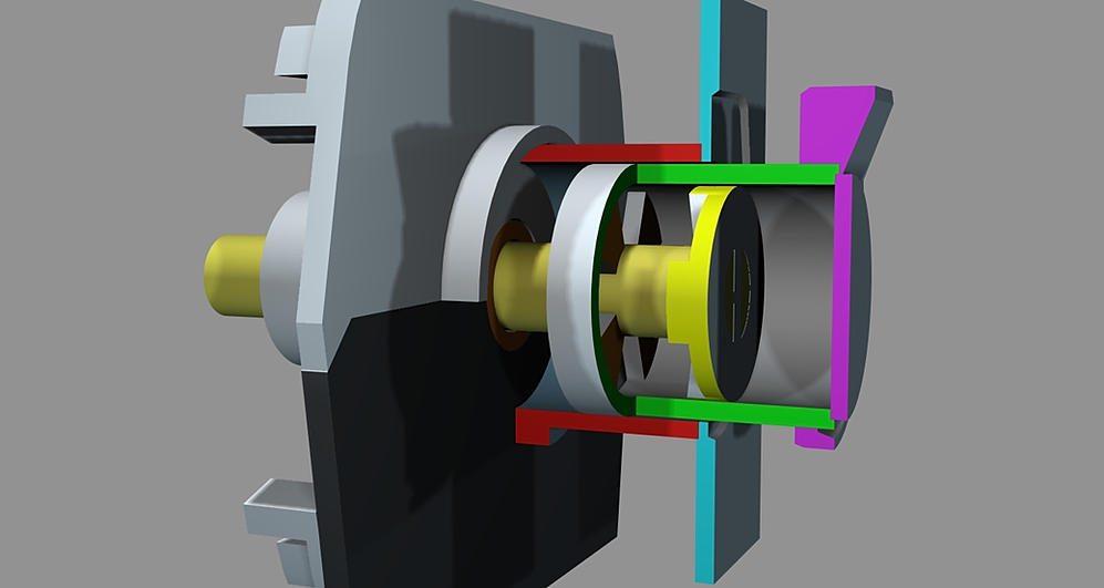
(Got it to work!)
It is the clearance between The Red and Yellow parts with the Green inbetween that will be tricky. The Green part attached toteh servo hub "Hatch" slides back and forth and is shown halfway inbetween snapped in place and engaging the Yellow driver clutch. The Red part is attached to the back plate and is stationary.
Last edited by a moderator:
trooper
Sr Member
forgiver me if ive missed it, but in your conversation I don't see any mention of mold shrinkage, and mold expansion/shrinkage due to temps.
something I learned the hard way when I made the molds for the lens parts on the macrobinoculars . trying to get the parts to fit together was tricky.
temperatures will effect the size of the molds when they are made as well as after. though not really detectable until you try to fit tight tolerance parts together.
I learned to pour all molds from the same silicone batch. and if possible, pour the resin in the same batch, though some times due to the amount of molds to be poured at the set up time of the resin it cant be done.
Last edited:
Hagoth
Sr Member
Thanks for your insights Trooper. Mold size changes is not something I had considered. That does further complicate things. I have more experience with injection molds but then it is a lot easier to duplicate the proper conditions each time and get consistant results with that method. I just took it for granted that the mold size would be a constant untill now.
At any rate I plan on having someone else do any casting molds for me as I have little experiance with rubber and resin. This does throw quality a curve ball in a way. Does it all need to take place in a climate controled environment?
Now that I have my 3D printer up and running, for the most part, I might just print these at as low a cost as I can. There are some features like the wire channels that can't be cast all the way but work very well 3D printed.
It's clear I still have a long way to go and a lot of hurdles to get over. I'm glad there are forums like this that offer such great support. :cool
Last edited:
trooper
Sr Member
I went back and looked at your video now that my internet is working good , and now that I see what the parts are, I don't think your dealing with such tight tolerances that you really need to worry about the mold or resin shrink differences
depending on what resin you plan on using, I prefer smooth cast 300 from smooth on, it has a shrinkage of .01 %
I also use smooth-on's mold max 30 which has a .001 shrinkage
I seen that alumilite has a new resin that has a hardness of 80d, thats hard! I have used the clear resin, but in order to get that kind of hardness you had to bake it. im going to try some.
http://www.alumilite.com/store/p/932-Performance-80D.aspx
those wire channels can be cast in and through the parts
Wow!,
Just read this Thread,
Fascinating design you got there Hogoth!
Nice work!
Mike Salzo was telling me the specialized resin he has to use for the V4 hinge components is a bit of a paint to deal with, but you need the strength.
(of course 1/24 scale is a lot more demanding in stress than the MPC 1/48)
It sounds like the perfect product to sell on Shapeways ( or a similar site), plenty of material options that the right properties in Shore Hardness & Strength
This has nice potential
rbeach84
Sr Member
Hagoth, I see that a looser 'fit' is probably okay with the telescoping parts, as long as its not so much as to cause binding. Also, you probably could get away with partial tubes [the green & red parts] -i.e., tubes with cutouts- because they primarily function to align the clutch plates. If your cutouts leave 'end rings' so to have a continuous surface at the point of engagement, then it still allows for smooth, supported operation yet would require less volume of material. Of course, the green tube shaft would need to retain sufficient strength because it shares the torque load with the primary shaft when engaged. Don't forget to allow for venting, in case the tolerance becomes 'airtight' - especially if you are considering allowance for lubrication.
Again, if the mounting space tolerances become too tight in certain implementations, there is always the option to discard the clutch and just have a 'pop-top' hatch and Allen wretch or Torx socket to engage an external operating tool. The goal of having the *very cool* remote operation using a motor might be possible if the motor & drive was at the forward end of the shaft, located in the 'cargo bay' area of the model. Certainly possible with the larger X-Wing models where there is more space to work with.
Fascinating project; I'm glad it is going so well.
Regards, Robert
newmagrathea
Sr Member
Just a thought about the back plate on X-wings. On red 5 (Luke Skywalker's) X-wing the little hatch points downward unlike the rest of the X-wings, including the way that the MPC is molded. With your design could the hatch be attached the other way.
Here is a pic of the back plate of Red 5.

Here is a pic of the back plate of Red 5.
Hagoth
Sr Member
I went back and looked at your video now that my internet is working good , and now that I see what the parts are, I don't think your dealing with such tight tolerances that you really need to worry about the mold or resin shrink differences
depending on what resin you plan on using, I prefer smooth cast 300 from smooth on, it has a shrinkage of .01 %
I also use smooth-on's mold max 30 which has a .001 shrinkage
Thanks for the feedback. This is very good information as the shrinkage rates are well below my required tolerances especially on parts this small. These manual parts could work very well as resin cast parts.
rbeach84
Sr Member
I bet that picture was taken after the part was stuck back on (incorrectly) when the mount was removed (eh-ah! that smarts!) But does that make it "canon"? ;^PJust a thought about the back plate on X-wings. On red 5 (Luke Skywalker's) X-wing the little hatch points downward unlike the rest of the X-wings, including the way that the MPC is molded. With your design could the hatch be attached the other way.
Here is a pic of the back plate of Red 5.
View attachment 467495
R/ Robert
Hagoth
Sr Member
... those wire channels can be cast in and through the parts
Hi Trooper,
I certainly hope so! Here are two pictures of the wire channels going through the part. Aside from the channel which is 0.5 mm deep and 1.0 mm wide passing 8 mm through the part, there is the part itself with the two parallel rings.
Here are the wires inserted into the channel passing through the body and the place holder wing root/engine box wall.
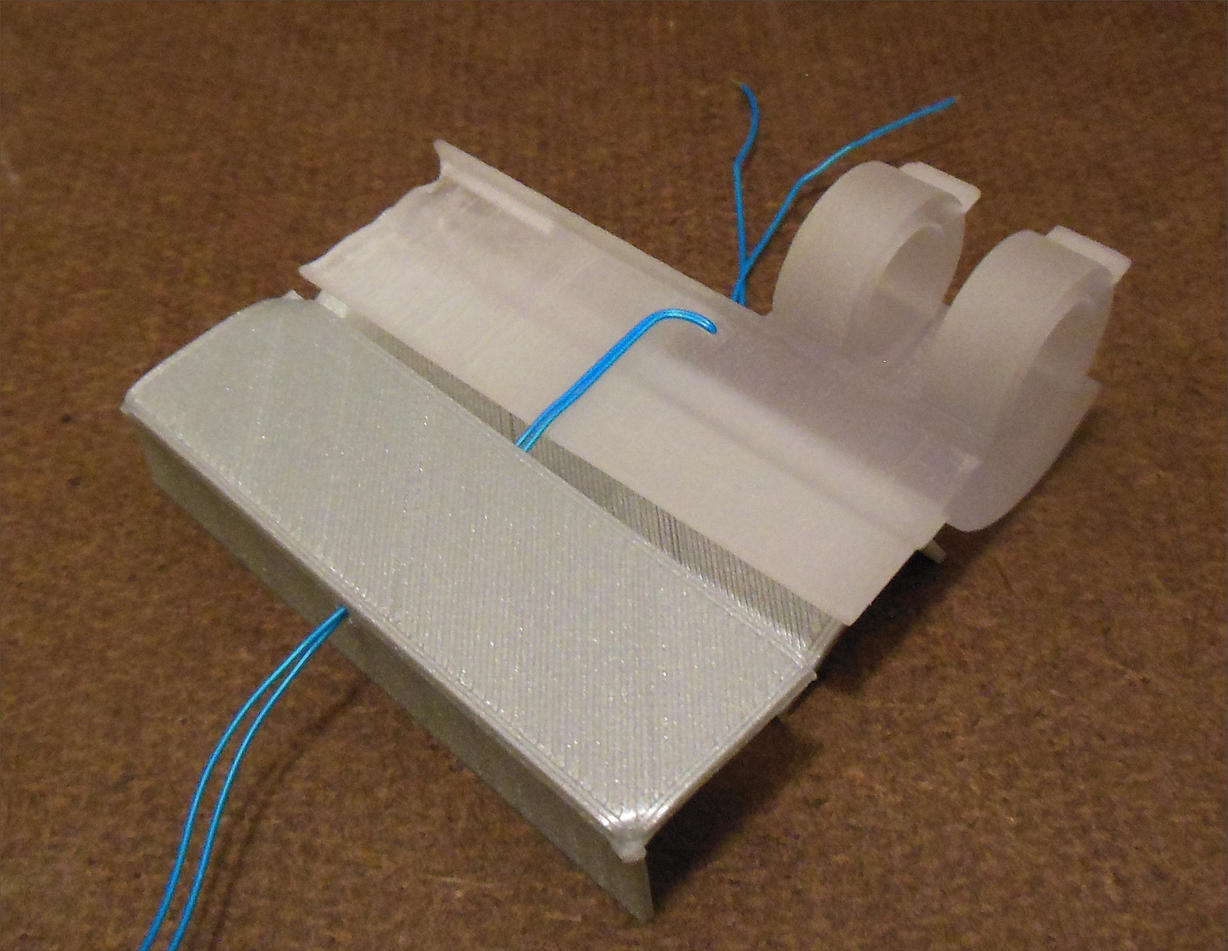
Here is where the wires are buried with the ends passing through the top and into the engine box. It is that 8 mm section that I'm not sure how to cast.
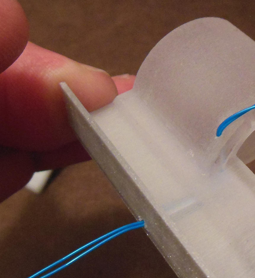
Any insight you can give would be much appreciated as my locally sourced caster may not work out.
Similar threads
- Replies
- 10
- Views
- 423