Round 2 Commlock mod with all the bells and some of the whistles, I hope...

teslabe

Sr Member
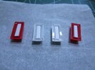
Just received the new Round 2 "Space 1999 Comlock and Stun Gun" kit and will be doing the same mods that I did on my cast resin props, this is the first in the series of videos for the build, I hope everyone who want to do a functional Comlock gets something from this and the future videos. I hope this is the right forum to post this build in.....:unsure:
 
You still have some of those video walkie talkies?
Yes, I have 6 pairs, including the pair we used for software rewrite/flashing and one single unit, but I just bought a single unit with a bad battery compartment for about $11.00 off ebay, I hope it works....
 
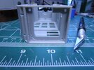
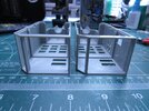
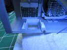
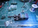
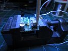
Got a little work done before I paint the body and the buttons, also posted a long rambling video to show how I'll be doing some of the mods.
More to come.....
 

Attachments

  • R2 Comlock mod01.jpg
    R2 Comlock mod01.jpg
    259.1 KB · Views: 82
  • R2 Comlock mod05.jpg
    R2 Comlock mod05.jpg
    245.3 KB · Views: 91
  • R2 Comlock mod06.jpg
    R2 Comlock mod06.jpg
    246.7 KB · Views: 85
  • R2 Comlock mod07.jpg
    R2 Comlock mod07.jpg
    231.5 KB · Views: 99
  • R2 Comlock mod08.jpg
    R2 Comlock mod08.jpg
    273 KB · Views: 92
  • R2 Comlock mod15.jpg
    R2 Comlock mod15.jpg
    301.3 KB · Views: 90
  • R2 Comlock mod16.jpg
    R2 Comlock mod16.jpg
    217.2 KB · Views: 103
Here is an old video from my first Comlock build using a resin kit, but is the same mod to the Spy Gear Video Walkie Talkies that are going onto the Round 2 build, seems silly to do another video when nothing is changing with this part of the project
 
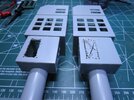
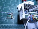
It doesn't look like I got that much done, but building the sub-assemblies take up a lot of time and have some needed parts slow to arrive isn't helping, but I did get the painting done and that's a big help...
 

Attachments

  • OLED Display mod01.jpg
    OLED Display mod01.jpg
    251.3 KB · Views: 77
  • OLED Display mod05.jpg
    OLED Display mod05.jpg
    214.6 KB · Views: 64
  • R2 Comlock mod21.jpg
    R2 Comlock mod21.jpg
    258.6 KB · Views: 66
  • R2 Comlock mod22.jpg
    R2 Comlock mod22.jpg
    260.1 KB · Views: 70
  • R2 Comlock mod24.jpg
    R2 Comlock mod24.jpg
    223.7 KB · Views: 77
  • R2 Comlock mod25.jpg
    R2 Comlock mod25.jpg
    235.9 KB · Views: 71
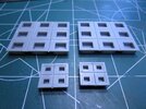
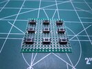
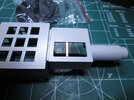
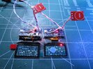
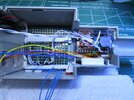
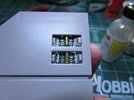
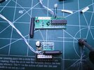
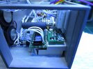
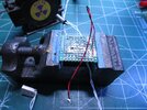
This post covers the mp3/keypad assembly for the Comlock, I used a DFPlayer for the base and made the keyboard out of some prototype board, keeping it as a single unit for easy install.
 

Attachments

  • R2 Comlock mod29.jpg
    R2 Comlock mod29.jpg
    388.9 KB · Views: 65
  • R2 Comlock mod30.jpg
    R2 Comlock mod30.jpg
    339.1 KB · Views: 63
  • R2 Comlock mod31.jpg
    R2 Comlock mod31.jpg
    273.7 KB · Views: 65
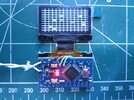
There is a lot of cutting down of the display's mother board if you want it to lay flat in the corner of the comlock, it needs to bethe same size as the OLED display itself. It's not that hard, just take your time....
 

Attachments

  • OLED Display mod08.jpg
    OLED Display mod08.jpg
    302.1 KB · Views: 62
  • OLED Display mod09.jpg
    OLED Display mod09.jpg
    305.3 KB · Views: 59
  • OLED Display mod10.jpg
    OLED Display mod10.jpg
    355.4 KB · Views: 58
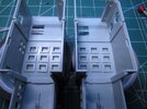
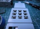
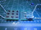
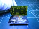
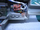
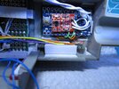
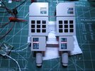
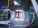
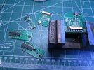
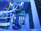
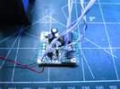
Got all the buttons I wanted to be tactile installed and the DFPlayer/mp3 player installed along with the three buttons for the Spy Gear Video Walkie Talkie's menu interface, next comes the installation of the Spy Gear electronics....:)
 

Attachments

  • R2 Comlock mod34.jpg
    R2 Comlock mod34.jpg
    266.1 KB · Views: 64
  • R2 Comlock mod35.jpg
    R2 Comlock mod35.jpg
    290.3 KB · Views: 61
  • R2 Comlock mod36.jpg
    R2 Comlock mod36.jpg
    306.9 KB · Views: 71
  • R2 Comlock mod37.jpg
    R2 Comlock mod37.jpg
    310.4 KB · Views: 69
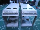
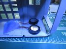
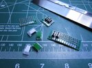
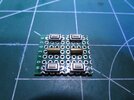
Some detail on the last buttons I'll be modifying for the Comlocks, these are for the video transceiver's "push to talk", the geiger counter power switch and the 4 channel remote control.
 

Attachments

  • R2 Comlock mod39.jpg
    R2 Comlock mod39.jpg
    327.3 KB · Views: 64
  • R2 Comlock mod45.jpg
    R2 Comlock mod45.jpg
    291.7 KB · Views: 60
  • R2 Comlock mod44.jpg
    R2 Comlock mod44.jpg
    240 KB · Views: 72
  • R2 Comlock mod46.jpg
    R2 Comlock mod46.jpg
    236.2 KB · Views: 60
This is just an update of the build and a little more detail of what was done for the last two switch mods.
 

Attachments

  • R2 Comlock mod43.jpg
    R2 Comlock mod43.jpg
    257.4 KB · Views: 71
  • R2 Comlock mod42.jpg
    R2 Comlock mod42.jpg
    259.9 KB · Views: 62
  • R2 Comlock mod41.jpg
    R2 Comlock mod41.jpg
    264 KB · Views: 69
  • R2 Comlock mod40.jpg
    R2 Comlock mod40.jpg
    273.1 KB · Views: 64
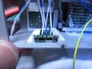
This is part one of the installation of the remote control that I'm putting in the comlocks. Had a bit of a issue with the encoder/decoder set, I found that the encoder needs to cycle power for each key stroke, makes sense since this pairs are found in battery operated remotes.
 

Attachments

  • R2 Comlock mod50.jpg
    R2 Comlock mod50.jpg
    308.2 KB · Views: 60
  • R2 Comlock mod48.jpg
    R2 Comlock mod48.jpg
    388.3 KB · Views: 66
  • R2 Comlock mod47.jpg
    R2 Comlock mod47.jpg
    350.3 KB · Views: 53
This is part two of the building, testing and installing of the remote control for my Comlock.
 

Attachments

  • R2 Comlock mod52.jpg
    R2 Comlock mod52.jpg
    218.3 KB · Views: 58
  • R2 Comlock mod53.jpg
    R2 Comlock mod53.jpg
    330.5 KB · Views: 58
  • R2 Comlock mod54.jpg
    R2 Comlock mod54.jpg
    258.4 KB · Views: 54
  • R2 Comlock mod55.jpg
    R2 Comlock mod55.jpg
    296.4 KB · Views: 64
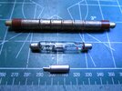
It's been a few weeks since the last update, I set the project aside as I had a bit of an issue with the smallest GM tube for the Geiger Counter that is going into the Comlock, it had very little volume and the red LED was very dim. I ordered parts and just received them last week. The mod I need to do to the circuit worked so here is the update. I'm posting the schematic for the Geiger Counter circuit without the mods I made since it's only relevant if the SBM-21 micro Geiger tube is used, also, don't ground the output of the transformer as shown in the schematic, as I believe it's an error.
 

Attachments

  • R2 Comlock mod56.jpg
    R2 Comlock mod56.jpg
    283 KB · Views: 42
  • R2 Comlock mod57.jpg
    R2 Comlock mod57.jpg
    287.9 KB · Views: 44
  • Geiger Mueller tubes.jpg
    Geiger Mueller tubes.jpg
    305.8 KB · Views: 44
  • G24846.pdf
    156.8 KB · Views: 70
Last edited:

Your message may be considered spam for the following reasons:

If you wish to reply despite these issues, check the box below before replying.
Be aware that malicious compliance may result in more severe penalties.
Back
Top