Hello,
I am still struggleing with some of the parts for the front madable walls and the engine deck, so no updates till i get something I am not embarrassed the show. I am hopeing to be less crap at it in the near future.
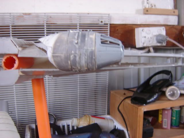
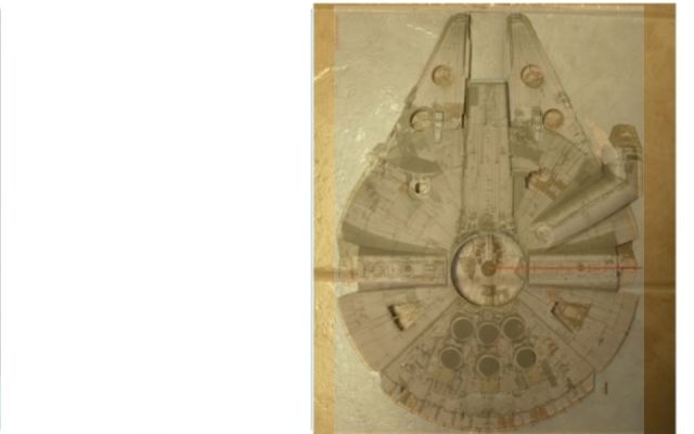
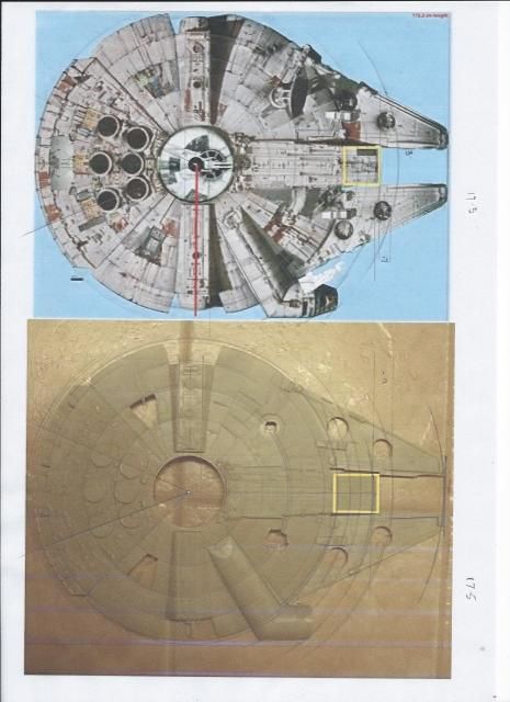
In the meantime I have hacked away at the body of the falcon to see if the new measurments I am comming up with (based on the parts I am making that are used muliple times around the ship) to see if it looks right.
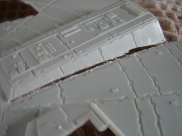
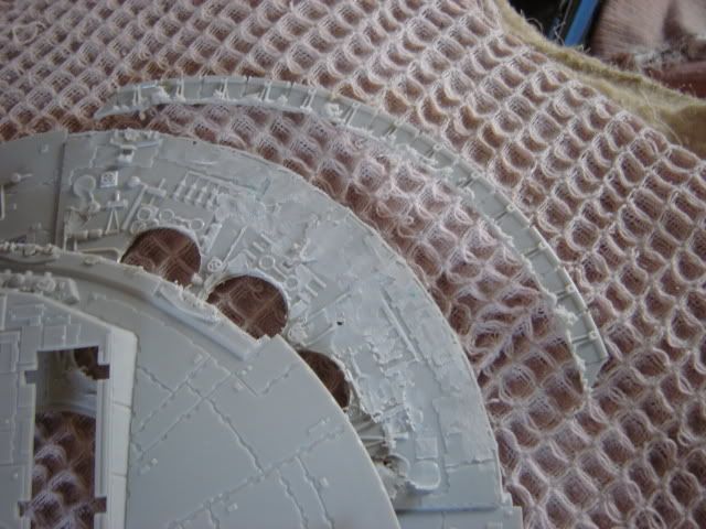
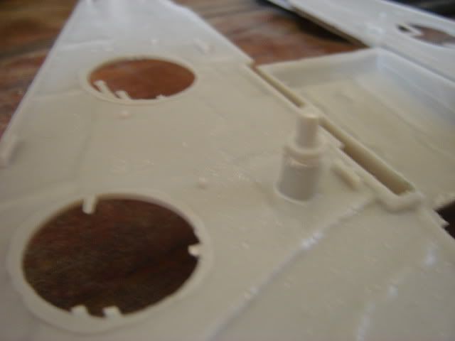
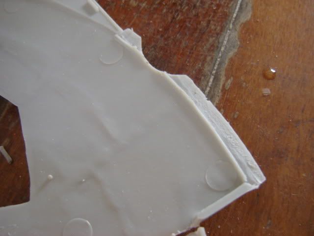
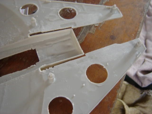
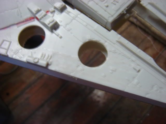
First of all I cut the parts that would be most affected by the "hambergering" of the body. The docking ring halls, and the cockpit tuble.
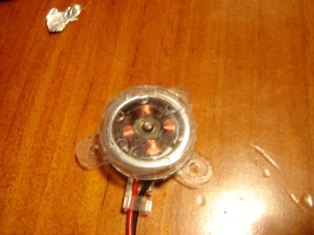
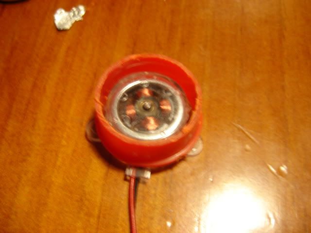
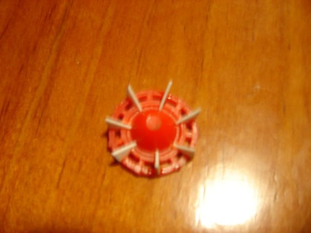
Then I cut off the fin section at rear (I will be replacing with new ones) and the lower front landing bay (which is tooooo shallow), and the engine exausts on the engine deck. I had planed to reuse these, but I am going to make some new one with actual moving mini electric fans inside them ( ya ya I know dream on LOL.)
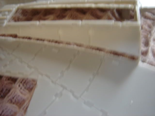
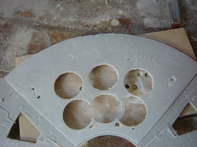
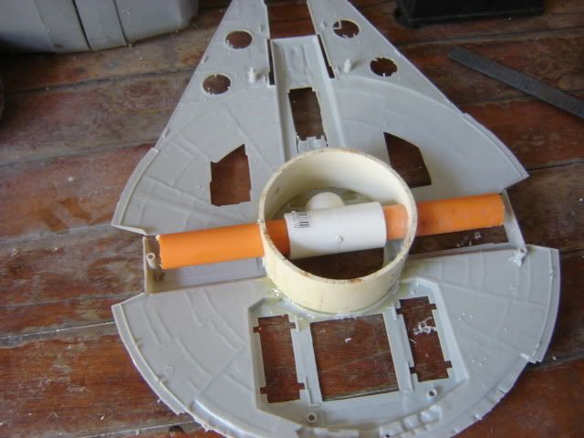
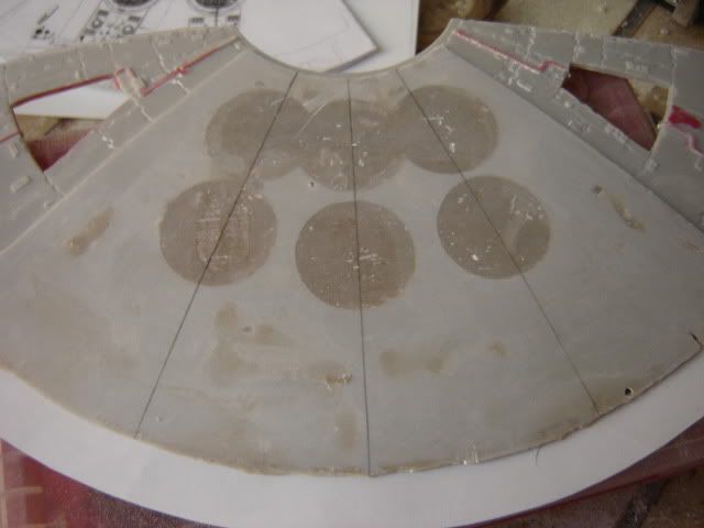
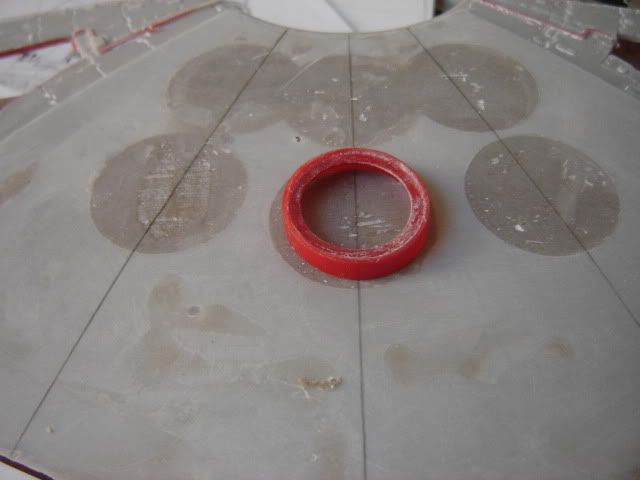
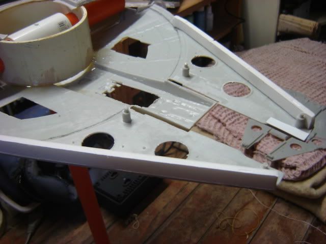
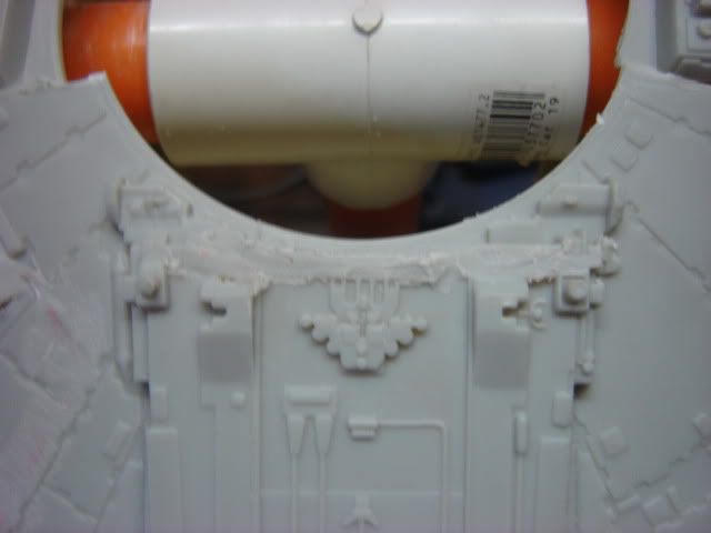
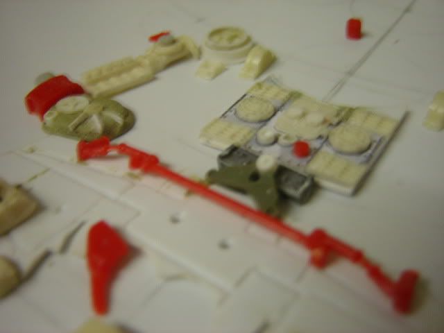
this is the correct size for the tank deck. Landing bay box to be sized around it.
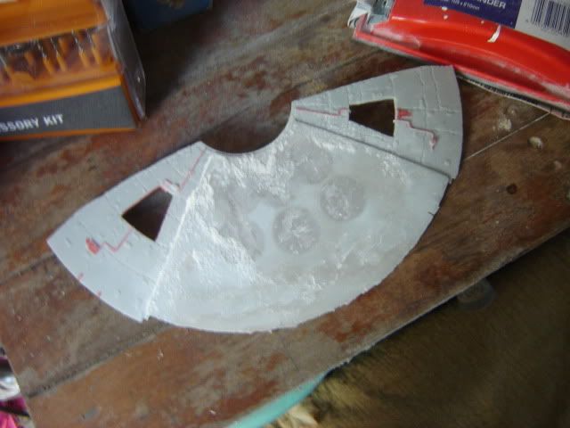
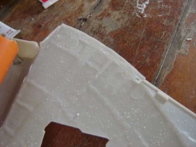
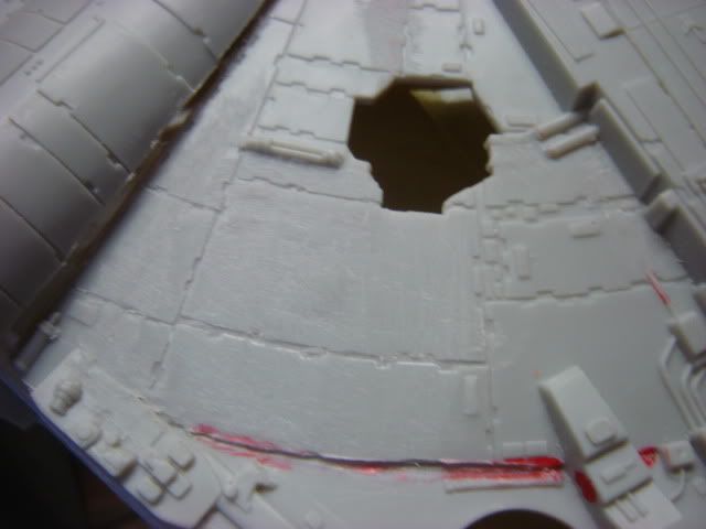
Next sanded down the engine deck.
Undecided as to whether to do the drop on engine deck, removable or just greable this. Anyone been here before have an opinion?
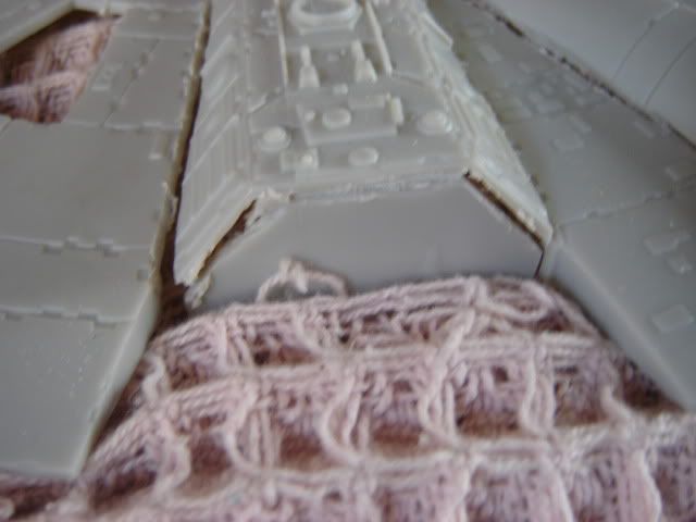
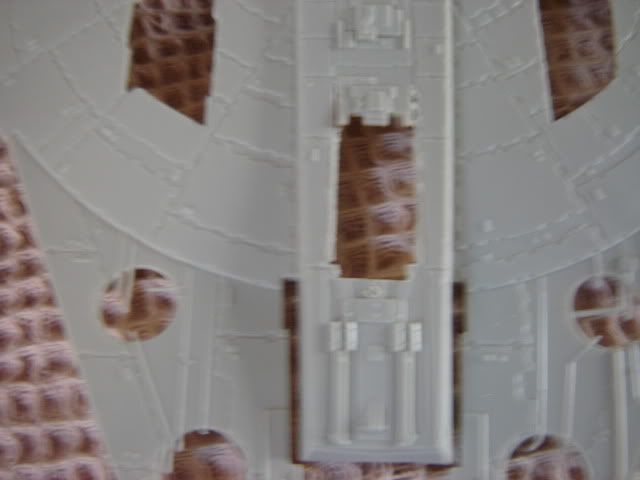
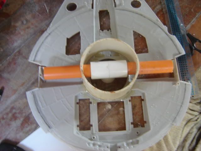
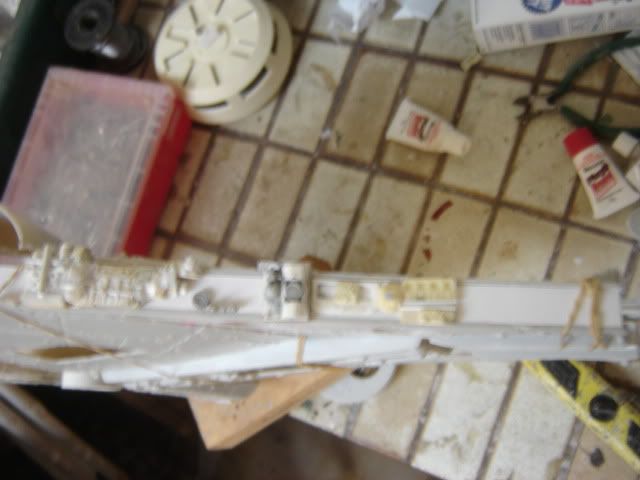
Ok next I put in the burger spacer and some electrical conduit for attaching the falcon in different possitions. I used 20mm2 heavy duty conduit so I can put what ever I can find as the side/bottom attachments. I dont have a clear solution yet.
I only attached it to the bottom for the moment so I can figure out what wiring is going into it.
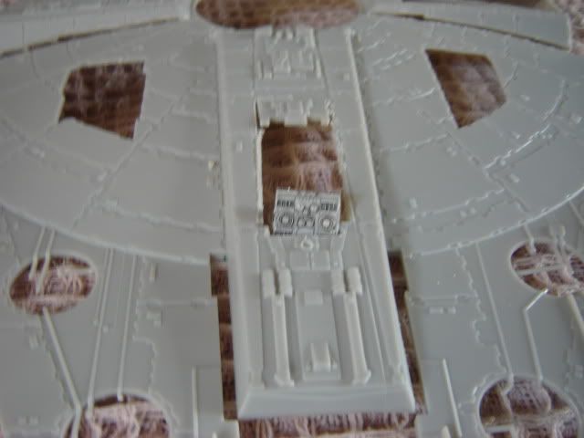
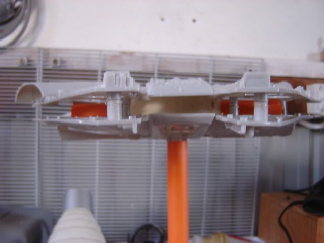
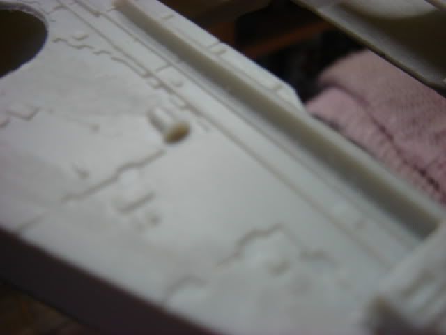
Next (after24 hours waiting for the apoxy to dry) I lowered the height of the spacers around the body to mach my new side wall height of 1.6cm. This is an increase of 1 cm from my original falcon. Ohh and the spacer is 5cm. The spacer is also a change and represents the docking ring size (which I have estimated) matching the walkways being level (does that make sence?)
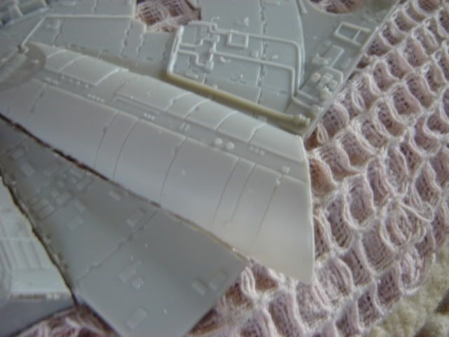
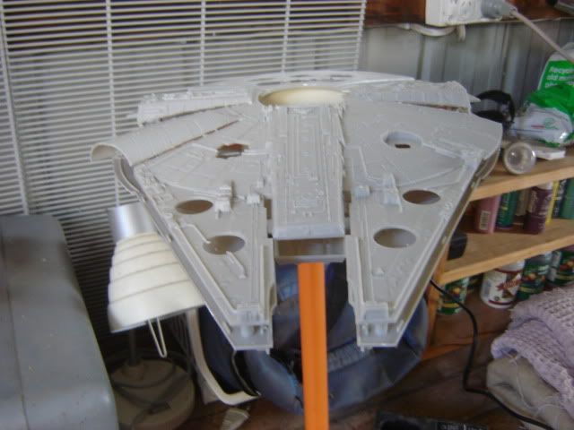
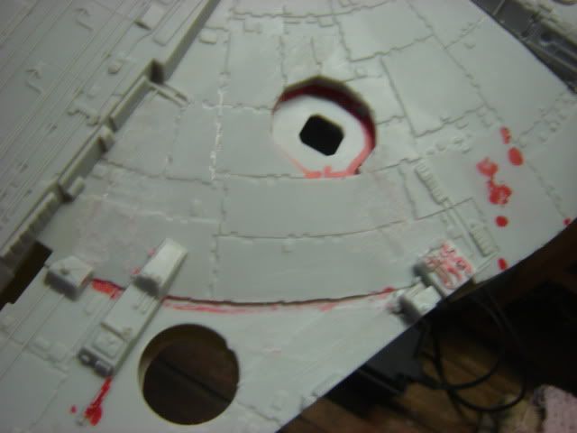
OK, fitting top and bottom. With the cockpit as well to see how it looks against the side wall height.
Well thats it, even though I have made estimates to try and ensure I get the right sizes for the falcon to be a good representation of the 5 foot falcon, I am also relying on phot reference to see that it has the same look against my own photo's. Not science I know, but the ultimate end result for me is a falcon that "looks" like the 5 foot.
Thaks for looking
Ozzy

") thumbsup
thumbsup