Randy Cooper Smuggler Ship

Muzza

Sr Member
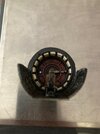
Received a few weeks ago the kit of Randy's the Smuggler ship.
Some one out there will know the history better than me but I did hear this was the original concept ship for the Millennium Falcon.
Here are a few of Randy's Build photo's of the ship.
312135534_10160408868035238_4835494151092155371_n.jpg312219346_10160408868170238_7978808038432634897_n.jpg312469629_10160408869040238_5712990990150431511_n.jpgRanndy's photo 1.jpgRanndy's photo 2.jpgRanndy's photo.jpg

This is a very sleek looking ship.
 
Last edited:
Wow this kit goes together so easy even with out glue or tape.
Here it is just picking the parts off the table and sitting on the engine block.
b.jpg
The engines always look to be the hardest to put together but the way this is designed it took only 10 minutes to assemble for the photo.
D.jpg

Randy even supplied a Jig to align these bad boys.
 
Here’s a model of ‘Han Solo’s Pirate Ship’ I built for John Simmons during Lockdown (2020) using the Korbanth Runner & DeAgostini Falcon casts

Model is painted by its owner John Simmons:

33D2ED3E-9A5F-46F6-B8D6-8A39F6BB6F3E.jpeg
01112E89-DCA6-472C-85A0-21822D7864FE.jpeg
3629CB97-96E9-4797-B453-967B9D28F64E.jpeg


BC401952-BF25-4ECE-98B1-82AFC0F2860D.jpeg
C6D532B4-71C5-43C0-9946-C8F803D05EBA.jpeg
ABAD04F6-5C47-4694-B38A-10E09058A000.jpeg
34627518-7995-4A6A-AA8E-81CB4CF81F8F.jpeg


A history & video about The Pirate Ship & this model can be viewed here:


John
 
Here’s a model of ‘Han Solo’s Pirate Ship’ I built for John Simmons during Lockdown (2020) using the Korbanth Runner & DeAgostini Falcon casts

Model is painted by its owner John Simmons:

View attachment 1634283View attachment 1634284View attachment 1634285

View attachment 1634287View attachment 1634288View attachment 1634289View attachment 1634286


A history & video about The Pirate Ship & this model can be viewed here:


John
Wow that looks fantastic!
It is good to see more of the more obscure / concept Star Wars ships starting to appear.
 
I have started on working on the side gun turret, I am working on adding some lighting but I will have to see how I go.

I have made a few changes to the parts supplied.
I have cut down the length of the turrets hall way so I can still keep my tube running through the center of the ship.
M.jpg

Here is the connecting door at the end of the hall way of the turret. I have machined the edge of the detail off so the door just clips into the end of the hall way.
L.jpg H.jpg O.jpg

We are supplied with a gunners seat and aiming console just like the one we see on the Falcon.
I.jpg

We are supplied with a opaque roof section for the turret so it can be light blocked on the inside then back light the exterior.
N.jpg
 

Attachments

  • J.jpg
    J.jpg
    551.4 KB · Views: 96
Engine alignment using the supplied jig.

ii.jpgjj.jpg

I have primed the inner 3 engines as it was easier to do while it was a part.

I might prime all the add on detail parts before gluing them onto the engines.
 
Lighting those engines.

Here are the LEDs I used for the engines
ss.jpg

First I glue the LEDs to the spacer you will have to drill a 5mm hole.
p.jpg

What I did is to use one of the detailed engine parts as a jig to hold the opaque light defuser while I glue the spacer.
q.jpgr.jpgs.jpgt.jpg

Just adding a little detail I did a little dry brushing to the opaque disc so when it is light up you can see a little of the detail.
u.jpgv.jpgw.jpgx.jpg

Once I had them all glued I cut off there tails and got them ready the wiring.
y.jpg
 
Great looking build - I'm a bit concerned about those LEDs though - the packet says 20mA 3-12V which does not make sense unless each has a built-in regulator that will deliver the 20mA over that range. I suspect they may just have prewired resistors, but those will only give you the 20mA for a specific voltage, not a wide range like that. It may be they are prewired to give 20mA at 12v which is fine, but any voltage under that you won't be getting full brightness. If they a prewired for 3v, then applying 12V will massively overpower them. Somewhere in between may initially "look OK" but still could be driving the LEDs to a very early grave.... I'd hate for them to start dying once they were all sealed up in the model!
 
Great looking build - I'm a bit concerned about those LEDs though - the packet says 20mA 3-12V which does not make sense unless each has a built-in regulator that will deliver the 20mA over that range. I suspect they may just have prewired resistors, but those will only give you the 20mA for a specific voltage, not a wide range like that. It may be they are prewired to give 20mA at 12v which is fine, but any voltage under that you won't be getting full brightness. If they a prewired for 3v, then applying 12V will massively overpower them. Somewhere in between may initially "look OK" but still could be driving the LEDs to a very early grave.... I'd hate for them to start dying once they were all sealed up in the model!
I will be using 12V power source and running the LEDs via a relay controlled by a arduino so I get a flicker to the engines.
I have ran these LEDs on 12V before and all are still going fine mind you it has only done about 24 hours, one show.
Thank you for the heads up, I usually test my LEDs before I install them, for at least one week. But I didn't do it this time but I am not worried as the end ends of the engines are glued with white glue so I can remove and replace them if they give any trouble.
 
Last edited:
Lots of space in the engine tube to hide the excess cable.

zz.jpg
Always test every line of LEDs at every stage Just to make sure they have been correctly connected.

z.jpgz1.jpg

Just to be on the safe side and I usually do this when I can, instead of gluing the rear engine part with super glue I use white glue or wood glue.
It may take 12 hours to dry completely but if any of the LEDs go out it is very easy to remove the end just with a hobby knife.
z2.jpg
 
Because I an have this ship landed I have made use of the side access door to be open.
I will add a ramp once I have it fixed to its base.
Before cutting out the door I took a mold off the area so I can re produce it and attach it in the open position.
I added some parts, floor and some padding to the inside of the door to make it look busy. I might add a figure in the doorway as well, later on.

zz1.jpgzz2.jpgzz3.jpgzz4.jpg
 

Your message may be considered spam for the following reasons:

If you wish to reply despite these issues, check the box below before replying.
Be aware that malicious compliance may result in more severe penalties.
Back
Top