Overwatch Genji Costume Build

Tempest Forged

New Member
Hi everyone.

So after years of lurking and absorbing the wealth of knowledge on the forums, I’ve decided to post my own build log of my Overwatch costume.

Inspired by the work of Kamui Cosplay and Bill Doran from Punished Props, I decided that for Halloween I needed a suit of armour. Being a fan of Blizzard games, one of their characters was a natural choice, but I wanted something a little bit more arbitrary, so a character from their game in development turned out to be just the thing.

One thing to note is that this costume was completed in time for Halloween last year (2016), before the official character was announced. Before then it was whispers and rumours about him and what he would be like. The only clues that I had were 2 screen grabs from the intro video and one image from the wallpaper that was put up.

Screen Shot 2015-07-03 at 7.02.36 PM.pngNinja1.jpgScreen Shot 2015-07-03 at 7.04.10 PM.png

As a result, I had no idea of what his back would look like, and, honestly it really didn’t matter too much as no-body was really going to pay attention to the back anyway. In retrospect, I think I made a pretty good prediction of the back armour.

If you’re interested, the link to the official cosplay reference kit is:

https://playoverwatch.com/en-us/media/

Another thing to note is that this is my first armour build that I have ever done. Yes, I know it isn’t great or amazing or close to anything that the epicness that floats around on these forums, but I wanted to show newbies that you can get a really good result with no experience.

The main advise I would give to anyone contemplating doing one of this costumes is just to go ahead and do it.

Plus, I learnt tonnes and had some fun running around terrorizing little children on the night, which is always a bonus.
 
Last edited:
Part 1: The Design

The first thing that I did was to print out the 3 references that I did have and examine them carefully. Having a medical background, I noticed immediately that the armour was based on muscle groups of the body, so I used that as a starting point. Due to how busy some of the pictures were, I decided to redraw the armour in a line drawing to clear up the confusion and get a better picture of the shapes of the individual pieces.

IMG_8432.JPGIMG_8433.JPGIMG_8434.JPGIMG_8435.JPGIMG_8436.JPGIMG_8437.JPGIMG_8438.JPG

After that I added annotations to help me with the armour colours and what joined where.

The next step was to start getting the pattern ready. As I was alone in this process, I used the good old cling film and masking tape method to create a body form of myself. Whilst wrapping myself, I made markings of important boney landmarks so that I could orientate myself when it came time to start drawing the pattern.

I side note to make over here: I did the body form of my left side for 2 main reasons. The first is that I’m right handed and it was just easier. The second is that the left side of the human body is actually the larger and heavier side so it would avoid sizing problems (or so I thought… - more on this later)

Whilst the masking tape forms were on me, I also tried moving around in an effort to distinguish the joint lines and to mark out were I wouldn’t be able to place any armour. A good example of this is the inner part of the elbow, where there is a diamond shaped portion of skin (called the ante-cubital fossa) that touches itself when the arm is fully bend. I had to avoid any amour over here as I would need to bend my arms to fully wield the sword around.

IMG_4284.JPG


Once the body forms were taped on, I cut them off and reassembled them. I then laid them out next to each other as they should have been connected. From there, referring to my reference pics, I sketched out where each of the armour pieces needed to go, and where they needed to connect to each other. Once I was happy with the overall look, I inked it with a felt tip pen. Off all the pieces, the chest and abdominal piece proved most tricky due to the proportions. Eventually, I stuck it back onto my body, and drew the lines whilst looking at a mirror.


IMG_4294.JPGIMG_4292.JPGIMG_4297.JPG
 

Attachments

  • IMG_4300.JPG
    IMG_4300.JPG
    1.2 MB · Views: 361
Next I marked each individual piece, took photos to make sure I could have some reference when I forgot how they connected, and then proceeded to cut the entire pattern up with a pair of scissors.

IMG_4300.JPG


From here I got some inexpensive brown paper, placed the masking tape pieces on and traced around them in pencil. Using a pen and ruler, I then cleaned up the lines.

Very early on in the process, I realized that due to the thickness of the foam, armour in the exact dimensions of a skin form would not fit me perfectly. What I found necessary was that I had to orientate the piece so that the circumferential length was lying horizontally. To each end point I added about 15-20mm, and then shifted all the points of piece proportionately. If you look carefully in the below images, you’ll be able to see what I mean.

IMG_4321.JPGIMG_4320.JPGIMG_4319.JPGIMG_4318.JPG

After that, all the brown paper pieces were labeled, cut out and then stored in a folder.
 
Part 2: The Foam Work

Then it was time to whip out the foam. For this build I used 12mm EVA floormat foam. They cheapest place that I could find it in Johannesburg was from Westpack.

Using the brown paper templates, I traced each of the pieces onto the foam and began cutting away with a retractable blade. Many hours and multitudes of scrap foam pieces later, I had all my pieces cut out.

IMG_4317.JPG

For some of the pieces, such as the forearm pieces, the cuts had to be made at an angle. Initially I did that freehand, but after getting inconsistent cuts, I decided to use my father’s scroll saw. It did wonders for cutting angles around curves, with the main downside being that it left a series of lines over the cuts. These were then cleaned up if needed using the sanding drum of a Dremel multitool.

For some of the forearm pieces, it was necessary to build up certain areas of the armour, in order to create the required height of the ‘muscular groups.’ (Again my medical side took over)

IMG_4383.JPGIMG_4374.JPGIMG_4385.JPG

Once the pieces were cut, I used masking tape to temporarily fix the pieces together so that I could fit them on. Needless to say, they didn’t work the first or the second or the third time. Most often, the pieces were just too tight, so I had to go back and alter all the templates. Painful and wasteful, but an important lesson that needed to be learnt.

Once I was sure of the fit, I began the carving using the dremel and the sanding bit. Thankfully, the majority of the carving was merely rounding off the edges of most of the pieces to a greater or lesser extent. In certain areas, lips had to be carved to allow the pieces to be joined together.

I used 2mm foam in the few areas that needed additional details. Most of the scoring lines and holes were done using a soldering iron.

Pieces were heat formed using a heat gun and in most instances were coaxed into their correct shape over my knee. The heat had an additional function of sealing the foam surface.

Pattex contact glue was the used to glue together the pieces that needed it. After the glue had cured properly, a final heat shaping took place. Some of the smaller pieces such as the lower portion on the pauldrons were glued on using superglue.

After joining, the seams were sanded down and filled in using Pattex acrylic sealant. This took plenty of attempts to get right but it did give a decent finish.


IMG_4449.JPGIMG_4450.JPG


Then it came time to cut out the circular holes – probably the trickiest cuts of the entire project. After searching through multiple hardware stores for a tube of the right diameter, one day whilst grocery shopping, I happened upon the perfect object: a can of Apricot Jam!

The can was opened, the jam scooped out into another container and progressively eaten. At this step it is important to note the type of can opener that was used: it is the type that cuts through the side wall of the can, liberating the lid as a whole. It doesn’t cut through the join or the wall of the lid. This is important as this type of can opener leaves behind a very sharp edge – perfect for what was needed. The edge was further sharpened using a grinding bit on the dremel. The bottom lid was left in place to maintain circular integrity of the tube.

IMG_4421.JPGIMG_4431.JPG

Using the sharp edge, the can was pressed into the foam and then twisted in order to cut out the circle. The smaller circle of the abdominal piece was cut out in a similar fashion using a 50mm diameter PVC pipe.

Unfortunately, due to the technique that I was planning on using to light the rings up, I needed to heat form and assemble the foam first before any cutting could be done. If I had cut the holes first, with manipulation, the holes would have landed up being oval and distorted, making the costume look very wonky. Plus I suspect that the holes would have made shaping tight curves like pauldrons a bit more difficult.

So I landed up having to mark where the holes would go after the curves were in place. On the pauldron, this was done quite easily by cutting out 3 circles of brown paper, and then positioning them on the pauldron using Prestik (known as blue tack in other places of the world) until I was happy. Then two small strips of paper were cut. The first was placed over the joint line and the second connected the two lower holes. The jig was taped together and the circles then traced. Once that was done, it was a simple as taking the jig off, flipping it over and lying it over the joint line of the other pauldron to get the position of those circles.

Cutting of the circles was done on my knee, using a spare piece of foam to prevent my pants from being sliced apart.


IMG_4427.JPGIMG_4426.JPGIMG_4425.JPGIMG_4424.JPGIMG_4430.JPG

In order to get the bolt head detail for the smaller lower abdominal holes, a small piece of foam was cut into a hexagon, and a circle abraded into it using a sanding drum of the dremel. This technique is discussed in detail in this video by Evil Ted Smith

https://www.youtube.com/watch?v=ybxIjQVjXoM

This ‘bolt head’ was then glued down on a piece of 2mm foam and this was then glued to the back of the armour piece, resulting in a nice recessed bolt head.
IMG_4370.JPG

After all of this, it was time to start sealing the foam. I went with Rust Oleum’s Flexidip. I chose this over plastidip for 2 reasons. First, each can was about half the price of Plastidip, and secondly, the only place I could buy the Plastidip was about 50km away, compared to the hardware shop down the road that stocked the Flexidip. Plus, there was no stock of black Plastidip.

I think in total I gave each piece about 7-8 coats – I sort of lost track. Thankfully it did exactly what I needed it to. All in all, I used 4 full cans of the stuff. (Please note that this includes the helmet and sword that I will discuss later)

IMG_4475.JPGIMG_4474.JPGIMG_4476.JPG

Next came priming all the pieces. Initially, I was going to prime it flat grey or black and then spray the pieces silver. Fortunately, I found that the Rust Oleum spray paints have an inbuilt primer, so I was able to avoid that step. Each piece was coated approximately 4 times to achieve a decent finish. I landed up using about 1 and a half cans of the silver and less than half a can of the mirror chrome colour.

Once the pieces were dry, I mixed together black and silver acrylic paint to make a dark gunmetal colour, watered it down and then, using an airbrush, started darkening the edges. The effect of this was to give the pieces greater depth and to emphasise certain areas. In retrospect, using tube acrylics was a bad choice. Even watered down, they still managed to clog the airbrush, and formed tiny droplets on the surface instead of a nice fine fog. Thankfully they dried looking fine, but in the future, I’d much rather use a better quality paint like Tamaya.

Lastly, the pieces were gently weathered with the same dark gunmetal paint, a sponge and lots of kitchen towel. I didn’t really include any battle damage, as at that stage, I envisioned the character to be incredibly agile and able to dodge most attacks. Also, compared to other characters, most of his armour looks quite light and not able to withstand much. Maybe at a later stage, I’ll add some damage…

Lastly, fine details such as the recesses and circles on the forearms were painted in with black acrylic paint.

Unfortunately, because I was already rushing at this stage, I forgot to take photos of the pieces
 
Part 3: The Assembly and the Undersuit

Now that all the pieces were complete, it was time to attach them to my body. But I first needed to find something to hide all my skin.

After hunting around, I eventually settled on a long sleeved compression top and a pair of compression tights from Mr. Price Sport. As you can see in the pictures below, the colour and pattern weren’t what I needed. So I decided that black fabric paint was the answer.

07_1251010061_SI_11.jpg07_1251010061_SI_00.jpg

And boy was that the wrong answer. I think that the problem lies with the exact construction of the fabric. I thought it would be dabbing a bit of paint and it would cover the offending white colour. What happened instead is that the material absorbed massive quantities of the paint, so it had to be dabbed on in large globs. Secondly, the paint absorption was very uneven, and in order to combat that, I had to stretch the fabric a lot. What eventually landed up happening is that I stuffed plastic bags full of clothes and then stuffed those into the clothing to stretch it out before I could paint.

In the end, it looked okay, but the painted areas could still be easily seen. I was also meant to paint on a carbon fibre effect to mimic the muscle groups, but I ran out of time. When I did get back to it at the end of November, the test area looked awful so I decided against it.

As you can see below in the pic of the completed suit, the painted areas are still very visible;

IMG_4556.jpg

Again in retrospect, I made a big error in doing the undersuit the way I did. If I had to do it now, even with trial and error, sewing an undersuit from scratch would be faster and the result would look better. Ideally, once I’ve gotten better at sewing, I’ll have an undersuit custom printed.

As for the gloves, I used a tutorial I found on the internet, and sewed them myself. They turned out really good if a bit small, but they were adequate for my purposes.

The balaclava was made using the same set of tutorials, but I underestimated how large a cut out hole would expand to. I was aiming for just my eyes to be showing and landed up with my entire face. But it was hidden behind a mask so I didn’t care too much.

http://www.stretchy.org/catsuits/options/gloves/
http://www.stretchy.org/catsuits/options/hood/


With the undersuit prepped it was time to get the harness done, for this I used 12mm (0.5 inch) nylon straps and elastics. Using the guide from Bill Doran’s excellent book, I sewed together the upper body harness. The pauldrons were attached directly to this by snap buckles. The chest piece, back piece and neck pieces attached to the harness by velco. To provide additional support, arm loops were attached to the pauldrons.

Elastic straps were used to join the two ends of the biceps together and this stayed in place with friction. I tried using velco to join the inside of the forearm pieces and it sort of worked but required constant readjustment. The knuckles were hot glued directly onto the gloves.

The thighs were just velcro’ed on and the shin pieces were connected in the same manner as the forearms.

The corresponding velco pieces were sewn on directly to the undersuit.

IMG_8441.JPGIMG_8443.JPG

Unfortunately, during most of this process I was rushed and didn’t get much time to take photographs. When I do have some free time, I’ll try and get some and add them in.

And that was how most of the armour was done!
 
Part 4: The Helmet

Like most helmets, this one was quite tricky. Mostly because I couldn’t get anyone to create a form of my scalp, I decided to go with more of a mask like approach. Using thin strips of 12mm foam, I made a headband and fitted it over the area of my head where I figured the final elastic strap would be going. Then using bits of paper I slowly modeled what one half of the helmet needed to look like. At this stage, I could only do one half as one of my eyes was covered by the brown paper.

When I was satisfied, I took the paper helmet off, drew in some details, cut off bits that I didn’t need, and the separated it into it’s components.

IMG_4350.JPG

These were then transferred to brown paper and then cut out of foam. When cutting the midline, I initially used an angle of 40 degrees. When glued together, the angle was way to harsh, and some proportions were out. Altering the template and cutting at a 20 degree angle gave the final shape. With some 2mm foam and a soldering iron, details were easily created.

IMG_4388.JPGIMG_4438.JPGIMG_4437.JPG

The problem that now arose was how to build the visor. Initially, the plan was to make it out of transparent plastic and then paint it with a transparent acid green paint. Unfortunately, the only paint that I could find that may have been able to stick to the plastic was the expensive mock-stained-glass paints, and I would have needed at least 2 bottles to do just the visor, never mind the rest of the costume.

At some stage building the rest of the costume, inspiration struck. I could build the visor as a transparent prism like structure, and use LED’s to light it up. By being clever and utilizing the concept of total internal reflection, I could divert the light out whilst getting none of it in my eyes – a win-win situation!

So I began patterning the visor prism. Because of its complex curves and a nearing deadline, I used scraps of paper, constantly adjusting until I had the right shape. I then transferred this pattern onto a piece of transparent plastic. As to the exact composition of the plastic, I have absolutely no idea what it is. It may be acetate oe acrylic or something completely different - my dad brought it home one day when I asked him to get transparent plastic to print on for something else. The beauty of the material is that nothing really stuck to it except for ink from one felt tip pen, and even that could be wiped away with some alcohol.

IMG_4464.JPG

The pieces were then cut out of this plastic, and then taped together to form the prism. It was then placed inside the helmet to check for fit and clearance from my eyes. Satisfied with this, I then filled the prism with my secret weapon: Silicon!

Before anyone gets too excited, this silicon is not the amazing mold making stuff – its commonly called silicon caulk, like the stuff you use to seal the edges of basins and showers with.

The exact brand that I used was Pattex transparent silicone. It was the only brand that I came across where the silicon was as clear as glass. Other brands that claimed to have transparent silicones had in fact translucent silicone, which would have been impossible to see through given the thickness of the visor.

Filling of the prism was straightforward if not messy. I tried my best to tape over as many joins as possible without impacting on the structural integrity of the shape. In order to prevent any air bubbles in the visor, which would have shown up immediately when the lights were installed, the tip of the caulking gun had to remain under the surface of the silicone at all times. This meant that the silicon had to flow into all the areas of its own accord – trying to move it with any tool would have trapped air bubbles. The nett result of this is that silicon oozed out everywhere, creating a monster mess, but in the end the prism was full.

Then the waiting game started. I left the piece outside next to the pool to begin curing. Only after 4 days did I even dare to touch it. Thankfully, the outer layer had solidified enough so that I could handle it. The excess silicone, having smeared itself all over the outside of the prism, was cleaned off by peeling it away and left over markings removed with rubbing alcohol.

The visor was left alone for a couple of more days whilst I was working on other pieces.

With the helmet sealed, primed and weathered, the headband was glued to the interior. Adding a couple of foam blocks helped support the front portion to stand proud of my face. An elastic band was connected to the back of the foam headband to held the entire thing on my face.

At this point I encountered another problem with the visor. What made it so amazing to work with also presented a challenge: how to attach it to the foam. Contact cement wouldn’t work, superglue made the plastic opaque, and double sided tape wasn’t strong enough. Then I happened to be watching a YouTube video where they used drawing pins to mimic rivets and I had the answer. I attached the visor on using drawing pins, and then to make it super sturdy, I coated the drawing pin’s shaft with super glue to lock it into place. The opaque reaction didn’t even show up.

IMG_4510.JPG

So now I had a helmet with a visor and couldn’t wait to try it on. When I did, two things happened. First, the helmet slid off my head – I had not banked on the visor being that heavy and the one elastic band wasn’t strong enough to support it. The second is that the view was like looking though a pair of drunk goggles – everything was distorted and walking became really difficult.

For the latter, nothing could be done, but to sort the former, I just added another elastic strap.

The last and final step was to install the LED’s. These were two small strips, cut from a much longer strip and wired together with a 12V battery pack and a switch. (More on the exact setup later). The LED was glued on using the same silicon, but set at an angle directed forward.

Three days later after the silicon had cured, it was time to test the lighting. Full of excitement at my own genius, I put the helmet on and switched it on…

…and was promptly blinded by the flood of green light!

Sad to say, my prism idea had not been as brilliant as I had thought. I could not see a thing, which meant that I would need to walk around without a helmet when I finally wore the thing. With nothing to do about that, I cursed at the fates and then carried on. Luckily, because of the straps, it was very easy getting in and out of the helmet.

However, there was some silver lining to this dark cloud. When I switched on the lights and looked at the front of the helmet, the green light emanating from it was much brighter than I anticipated. And when someone else wore it, I could only just barely make out their eyes.

IMG_4515.jpg

And so the helmet was done!
 
Part 5: The Sword

From the outset, I knew that the sword was going to be a complete mixed media project. As the two references that I had were slightly different, some design decisions were also going to have to be made.

Ninja Sword.jpg


Clearly, the most difficult part of the build was going to be the blade edge, and the fact that I wanted to make it light up didn’t help matters. But more on that later…

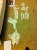
Back to the design of the sword itself, looking at the details, it appeared to be a modern version of a katana. The blade was curved, the handle proportionately long for a sword (fitting far more than 2 hand widths), and it lacked a pommel. The crossguard also appeared quite oval in shape. In my opinion, the additional tubes and blocks on the handle appeared decorative. The last clue was in the border between the green of the blade and the grey of the metal. This jagged line is very reminiscent of the curving line that is present on the blades of true katanas, denoting the division between different steel types.
Antique_Japanese_katana.JPG

(Pic from https://en.wikipedia.org/wiki/Katana#/media/File:Antique_Japanese_katana.JPG)

The sword type having been decided, I then had to decide on its size. Unfortunately, the two reference pics don’t provide much in terms of clues. I tried to measure the width of my hands and used that a scale to try and measure the length of the sword. Sadly that didn’t work out as Genji’s hands are slightly angled in the pic.

Spending time researching katana blades in order to get an idea of how to build the structure of the sword, I discovered that blade lengths depend on the height of the wielder. Using this information, I decided instead to make a sword that would look natural for my height instead of having fantasy sci-fi proportions.

Now that I had a length, I had to figure out what type of curve to employ. With true katanas, the shape of the blade follows a parabola instead of a circular arc. Thus the peak of the curve can occur on various portions of the blade, from close to the handle to close to the tip. From the side view that I had, it look like this peak was close to the tip, but the question arose of how exactly to trace it.

The solution turned out to be quite simple. Using Google’s Sketchup, I initially drew a single line to denote how long the blade would need to be from tip to crossguard. Next the reference pic was pasted into the programme and adjusted match the line. From there, the reference line was deleted and the outline of the blade and sword was traced with vectors. After removing redundant information, I was left with a very basic blueprint that could be printed out on a home printer and stitched together.

Screen Shot 2016-05-30 at 6.40.28 PM.pngScreen Shot 2016-05-30 at 6.41.01 PM.pngIMG_4410.JPG


With some of the dimensions now set, it was time to decide on how to build the sword. Sadly the internet is deficient on how to great good looking cosplay katanas, and no matter how hard I looked, I could find no tutorials on how to make a blade light up (short of lightsabers, but those are very specific builds).

Using what information I had at my disposal, mostly from Bill Doran and Kamui Cosplay, it was decided that the core would be made of a wooden dowel, covered in foam, with a PVC pipe forming the handle.

Now came the problem of bending the dowel. Again the internet wasn’t of much help, so I decided to get creative. Lacking a 2m long steam oven, I decided to submerse the dowel in our swimming pool for 48 hours in order to moisten the fibres. After that the dowel was placed between two solid supports, and a weight attached to the centre point, causing it to bow. This curve was made about a twice a severe as it needed to be, as the wood would rebound a bit when released. After 3 days of drying, I release the wood and had a curved dowel.

The dowel was then placed on the blueprint and moved until the curves matched up (more or less). It was then trimmed to the required length.

IMG_4462.JPG


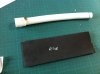
Next was the core of the handle. As this would foreseeably need to hold some batteries, it needed to be hollow. So in this case I used a PVC elbow connection. This was heated using a heat gun and then manipulated into the correct curve. Once the curve was correct, the entire tube was flattened slightly to give it an oval shape in cross section. This manipulation also strengthened the shape.

IMG_4472.JPG

The one end piece was left in place, as it would be hidden under the crossguard section of the handle. The other end was sawn off to length, but once that was done, a quirk presented itself. I found that the offcut, turned around, was able to slide over the cut. In effect, it made its own endcap. This was great, as I still hadn’t found a way to incorporate a battery compartment lid into the design, and this solved that problem.

So now onto the problem of the blade edge:

Inspiration for the build of this blade came from Kamui Cosplay and her build of Shadowmourne. The link to the video is below:

https://www.youtube.com/watch?v=McB0fSMyBWs

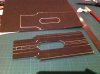
Following her method, the first thing to do was to get a 3D model of the weapon. As the character had not even been announced, nevermind the game being released, a direct model rip was impossible. As I have no experience in 3D modeling, I turned to Sketchup. Using the original blueprints, I arbitrarily decided to make the blade 20mm thick. I manipulated the blueprints to create one half of the blade, and then painfully exploded, reorientated and then stitched together all the facets into 2 long 2D drawings.

Screen Shot 2016-05-30 at 6.42.52 PM.pngScreen Shot 2016-05-30 at 6.43.56 PM.png

These were then printed out, and traced onto the same transparent plastic that I used for the visor. After cutting out the pieces, using Scotch tape, I stuck the entire thing together, eventually landing up with a beautiful hollow blade (minus the top). Additionally, I cut a strip of transparency for the back of the blade.

IMG_4435.JPGIMG_4436.JPGIMG_4472.JPG


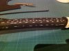
Now knowing the final dimensions of the blade, I could start on the foam for the interior. These were 12mm thick foam strips that had a groove carved into the back surface and got attached to the dowel rod with contact cement. Thereafter, the LED strip could be measured and cut to size, and was stuck onto the foam. The entire setup fit nicely into the hollow blade.

IMG_4465.JPGIMG_4463.JPGIMG_4467.JPG

During the dry fit, the square foam had difficulty sliding into the PVC handle, so that was rounded until it fit very snugly.

IMG_4500.JPG

Then came time for the silicon injection. Thankfully I had my father there to assist, which made life easier. I started injecting the silicon into the tip, and worked my way down from there, making sure to keep the nozzle under the surface in order to prevent bubbles.

After filling (actually overfilling) the length of the blade, I then slowly inserted the foam core, starting from the tip and lowering it towards the handle end. This process displaced the excess silicon towards the opening at the bottom of the blade. As all of this was going on, we also attached the transparency forming the back of the blade was also stuck into place, so that there wouldn’t be overlaps or areas that were sunken in.

IMG_4508.JPG

Once all the excess silicon was cleaned off, the blade was left for 7 days in the shade outside next to the pool. This was to allow for the fastest cure time. Unlike other chemicals, silicone caulk actually uses water in order to cure, so placing it in a high humidity environment helps to speed up this process. However, I would not recommend submersing it underwater – I in fact tried this with some test pieces and the results were better with air-curing.

Whist the blade was doing its thing, I worked on the handle. First to be done was the end, where the pommel would traditionally sit. A few scrap pieces of foam were glued together, the shape of the endcap traced and the entire thing cut out with a scroll saw. This end piece was then glued to the end cap. The shapes were then marked and rough cut with the scroll saw, and then I used the dremel to round everything off nicely. This was then covered with a single layer of foam to neaten it.

IMG_4480.JPGIMG_4477.JPGIMG_4481.JPGIMG_4478.JPGIMG_4479.JPG
 

Attachments

  • IMG_4482.JPG
    IMG_4482.JPG
    2 MB · Views: 248
  • IMG_4495.JPG
    IMG_4495.JPG
    2.3 MB · Views: 243
  • IMG_4498.JPG
    IMG_4498.JPG
    2.4 MB · Views: 271
Last edited:
When considering the design of the handle, it can be seen to be made of two layers, a black one and a grey one. This design made my life simple in that the handle could be built up in two layers of foam. The initial layer was glued onto the handle with contact cement, and the entire handle marked by eye for where the pattern would go. This was then measured and then transferred to a second layer of foam. A small slot was cut where the switch would sit. This was then glued onto the handle.

IMG_4495.JPGIMG_4482.JPGIMG_4498.JPGIMG_4499.JPG

Once the blade had cured, it was time to marry the two pieces. The wires for the LED strip were lengthened and fed through the handle. Then the base of the blade was covered in hot glue and quickly pushed into the handle, making sure the wires were clear. The blade and handle were now one!

IMG_4501.JPG

All the scotch tape holding the plastic together was now removed. Again the plastic posed a problem in that barely anything would stick to it. After multiple trials, my father suggested the use of double sided tape, which actually worked! So a pattern was created for the back of the blade, and the entire thing edged with double sided tape. This was then stuck down onto the blade and it worked a treat.

IMG_4509.JPGIMG_8425.JPGIMG_8426.JPG

A template for the crossguard was sketched on a piece of kitchen paper towel and cut out of 4mm foam before being superglued in place. The clear portions of the blade were then masked off in preparation for sealing and painting. Sealing was accomplished with Rust Oleum’s Flexidip and the piece spray painted with Rust Oleum spray paints. The piece was weathered slightly with black acrylic paints

IMG_4502.JPGIMG_8429.JPGIMG_8428.JPGIMG_8427.JPGIMG_8430.JPG

As for the electronics, it was a simple matter of connecting the wires of the LED strip to the switch and the battery pack. For this blade, I decided to use 3 12V 23A batteries wired in parallel. I initially wanted to have battery holders in the handle, but they got stuck, so I used duct tape to hold the battery pack together. The entire thing slipped into the handle, which was covered with the end cap.

And then the sword was complete!
 
Part 6: The Glowing Rings

I’ve decide to talk about these pieces in a section of their own due to the number of processes involved in their construction. I also suspect that future builders may struggle with this issue and this may help point them toward their own solution.

The difficulty with these rings lies mainly in their geometry. Firstly, they comprise of a number of circles, which are not the foam crafters easiest shape. Secondly, they have a number of bevels are circular in shape, and lastly the entire thing needs to light up. Finding cheap materials to accomplish this was always going to be difficulty.

Untitled.jpg

So onto their construction:

Firstly, the holes were cut in the armour pieces using a can of apricot jam, as detailed above.

Next came the problem of the glowing green ring. This ring had a bevel on the internal edge, which was an indeterminate angle. I decided on and angle of 45 degrees as it made the math simpler. Next, I decided that it should be 10mm deep, again to make the math simpler.

Now at this stage I’m sure that would look at this, scoff and decide to use expensive molding materials like silicon and resin. Unfortunately, due to their lack of availability and prohibitively high cost, I decided to not go that route.

What I decided was to mould each ring in silicon caulk, using a disposable plastic mould, and embed LED’s within the silicone. Initial trials proved successful and went ahead with the idea.

There were 12 rings in total in this build, and each needed a separate mold. This started off in the form of a plastic cone. These were made by tracing a circle in my ever-useful transparent plastic sheets, cutting them out, and bending them to a certain point.

This cone would form the bevel of the circle.

IMG_4434.JPGIMG_4439.JPG

I then cut a 10mm strip from the same plastic, and wound it around the apricot jam tin twice and stuck it down with tape.

IMG_4431.JPG


Then the two pieces were carefully stuck together.
IMG_4440.JPGIMG_4441.JPG

After that, I mixed up a release solution of dishwasher liquid (sunlight liquid in my case) and gently misted it into the moulds. I built up a number of layers to ensure that the silicon would release from the moulds, allowing each layer to dry thoroughly.

I then got the led strips ready. As luck would have it, the circumference of the ring would take exactly 12 LED’s. So each strip was cut, and wires soldered in place. These were tested multiple times to ensure that were in proper working order. The LED strips were then inserted into the moulds.

IMG_4461.JPGIMG_4459.JPGIMG_4444.JPGIMG_4442.JPGIMG_4464.JPG

After this, each mould was filled with the same silicon caulk as the rest of the project, making sure not to trap air bubbles. Excess silicone was scraped away, leveling a level surface.

In retrospect, I should have filled the bottom part of the mould first, then inserted the LED’s and then filled the rest in. Using the method I had, there were some areas where the silicon didn’t go all the way into the angle, which had to be hidden away later on.

The silicon pieces were left for at least 7 days to cure fully before unmoulding. They were then checked again to make sure that they worked – thank goodness they all had survived!

Whilst the silicon was curing, I turned my head to the centre pieces. These were also circular, and had a bevel. As anyone who has worked with foam might tell you, cutting circles is tricky already, but beveling a circle is even harder. Most of the advice that I got on forums was to cut out the circle as normal, and then bevel it by hand. However, this sounded like too much hard work for something that would come out looking average.

My solution came about in the form of a tip that Harrison Krix posted on his blog:

http://www.volpinprops.com/sophitias-elk-shield-soul-calibur-iv/

The way in which he sometimes cuts circles on his band saw is to make a jig to hold the centre of the circle stable, and then spins the material into the bandsaw and a perfect circle is cut.

What I figured is that the jig could be set at an angle and a circular bevel cut could be achieved.

So I set about recreating this to fit onto the scroll saw, and then tried it out. And it worked!!

However, I must say that there were some learning points. The first is that the back surface of the foam needed to be smooth, otherwise the circle wouldn’t be even. Second, the jig needed to be eased onto the blade – the saw couldn’t be started with the foam in the start position.

Third, with tilting the table, the edge of the circle shifts, so a new centre point needs to be drilled. Lastly, the scroll saw does leave teeth marks on the cut line, but these are cleaned up easily with some sanding.

After burning in some lines with a soldering iron, the centre pieces were done.

These were stuck down onto a sheet of 4mm foam, heat sealed, sprayed with flexidip and silver spray paint, and then weathered with black and silver acrylic paint.

Then came time to glue all the pieces together. For this, I used a small dab of silicon caulk, making sure to pass the wires through the foam beforehand. A heavy weight (a board) was placed on the entire sheet to ensure good contact, and then, yet again, the silicon was left to cure.

When I eventually lifted the board, I found that the silicon had partially dissolved the paint underneath, so that was a lesson learnt. Thankfully, it wasn’t noticeable, less so when the LEDs were switched on.

So then each ring was cut out, contact glue applied to the surround and on the inside surface of the armour and the rings jammed into their holes.

Lastly, the rings were wired to switches and battery packs that were then superglued in place. What I like about the LED strips is that they could be wired in parallel or in series, and the effect was the same, so I could minimize the amount of wire in different ways.

Sadly, again I forgot to take pictures of this process, but I'll try and upload some pics of the completed rings soon
 
Part 7: Conclusion

And that’s it for my very very verbous build.

I must again give a special thank you to the following inspirational artists whose online tutorials and blogs and books made all the difference in this build:

Svetland Quint (aka Kamui Cosplay) http://www.kamuicosplay.com/
Bill Doran (Punished Props) http://punishedprops.com/
Evil Ted Smith http://eviltedsmith.com/
Harrison Krix (Volpin Props) http://www.volpinprops.com/

And a very special thank you for reading about this build! Please feel free to PM me if you wish to know any additional information.

Cheers
Prav

Oh, and almost forgot, pics of the completed build:

IMG_4515.JPGIMG_4565.jpgIMG_4559.JPGIMG_4536.JPGIMG_4518.JPG
 
This thread is more than 3 years old.

Your message may be considered spam for the following reasons:

  1. This thread hasn't been active in some time. A new post in this thread might not contribute constructively to this discussion after so long.
If you wish to reply despite these issues, check the box below before replying.
Be aware that malicious compliance may result in more severe penalties.
Back
Top