I originally purchased this kit back in 2019 I think, with the intention of fully lighting it all up including working computer screens. I’d seen various commercial aftermarket parts and other inventive ways but all of those would add a significant cost to a kit price already way past my comfort zone so I wanted to come up with my own cost effective solution.
There are 2 major challenges to overcome when lighting this kit. Firstly there are a large number of banks of illuminated buttons on nearly all of the internal panels. These have all been molded in-situ as part of each panel, and each piece is in off-white styrene. It allows a certain amount of light transition from behind, but requires quite a lot to be effective. In other builds I’ve seen, blocking that light from where it’s _not_ required then becomes a significant additional problem. It would have been a much easier build if the buttons had been molded in clear as separate blocks to be mounted through the panels, but I guess the was not done for reasons of cost on an already expensive kit.

(Side panel components)
Secondly whilst small LCDs that can be driven by microcontrollers are available, they are generally still bigger than the pod screens, and would obscure some of the button lighting if mounted directly against the back of the pod panels.
Initially I found some bare LCDs that could provide a viable solution. For the 2 screens at the front of the pod, there are no adjacent buttons and this gives more room to work. The holes for the screens are 18mm square and I found some LCDs that were 18mm x 28mm. One of these could be mounted easily behind each hole.

(Small LCD)
For the other 2 pairs of screens it was trickier. They were arranged closely side by side but sadly the 18 x 28 LCD was too narrow to be used horizontally for both. The smallest one I could find that would cover a pair screens was 42mm x 32mm - but it was still significantly bigger than necessary and would definitely cover some of the buttons that needed lighting.

(Large LCD)
I continued on for a while, prototyping some electronics to drive the LCDs from an Arduino, but struggled to get the bigger LCDs working – mostly due to the hideously tiny 50 pin connector with a 0.5mm pitch which was almost completely beyond hand soldering, even with a hot air station.
I was also struggling with lighting the buttons – I experimented with 3d printing some light boxes to go behind each panel, but was also being put off by the things I’d read about how tedious and difficult it was to mask all the buttons when painting the panels, and how near impossible it was to apply the panel decals afterwards due to their fragility and inability to slide them into place over the raised buttons.
So eventually after a few months fiddling I gave up! I put the kit back in the cupboard where it stayed for the next few years until last summer when I tried to sell it off at a show – I didn’t really have much interest in building it as is with no lights.
On returning from the show - still with the kit, I randomly started looking around to see if there had been and advancements in the LCDs available and to my surprise there had been. You can now get a bare LCD that is exactly 18mm x 18mm, has a much more manageable connector and only costs a couple of quid a pop! I designed a small PCB that could be mounted on the back of the LCD and which exposes the necessary connections with a small socket.

(New LCD Front)

(New LCD Back)
So with the screens largely sorted, I went back to thinking about the button lighting. Something I had mulled before was cutting out all of the buttons from the panels, and replacing them with 3d printed buttons printed in clear resin. This would ease the lighting requirements, remove all the painful masking and also ease the panel decal application significantly. However, I really didn’t want to have to cut out _all_ the buttons. It would be a really tedious job, and also very hard to get neat, straight and square results. The way the panels were molded means the plastic is twice as thick right along the periphery of each button. ParaGrafx have a very good photo-etch solution which has brass panels with cut-outs that you can place over the buttons – which would also mean you could be a lot less accurate if removing the buttons since any issues would be covered by the brass plate. However it was still prohibitively expensive.
One other change that had occurred in the intervening years was the purchase of a much larger resin printer. I had thought about reprinting the panels with my FDM printer but the surface finish would still need a lot of work. My original resin printer was very small and not up to this task. My CAD skills have also grown significantly over the years so I started to tinker with duplicating some of the panels in CAD. The pieces are fairly complex – there are many angles, curves, tabs and slots allowing the pieces to be assembled into a very complex internal cockpit structure.
Trying to reproduce these by eye was very difficult – just taking measurements was hard with the limited tools I had. After a few test prints, I decided on a new approach. Instead of trying to duplicate the kit parts individually, I would try and make whole assemblies. Each side of the cockpit is made from 4 separate panels but it was actually easier to model them as the complete assembly. Angles were easier to measure, and I didn’t need to bother with all the interlocks holding them together.

(Side panel assembly)

(Side panel with other cockpit pieces)
There was still a lot of trial and error, but each iteration got closer until I had once side pretty much the correct shape. Since the other side is just a mirror image, it is simplicity to create this from the first side.

(Single 3d printed side panel)

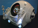
(Printed side panel in situ)
I did shoot myself a bit in the foot however, since I got carried away and started modelling the button holes too before I’d locked in the panel arrangement completely. The buttons are different on each side, so when the mirrored side is created I will have to go back and rework some of the button holes again.
Taking a break from the model over Xmas, I’ve been working on the electronics. The new screens are really nice, with just a tiny bit of extension at the bottom of the active LCD area where the flexible connector comes out before it folds round to the back. Mounting them upside down on the side panel means that only a small bit of a single button is obscured by each LCD assembly but there should be more than enough to allow button illumination.

(LCDs from behind – PCB not folded down)

(LCDs from front)
Initial experiments were with an Arduino Mini – I’m most used to the ATMega family of microcontrollers, and while I could get it to read an image file from an SD card and show it on one of the displays line by line, the limitations of the chip were obvious – it was slow, and that simple example used almost all of the available RAM. I was going to need something much more powerful. As luck would have it I had a spare ESP8266 dev board I’d just been using for some RGB xmas tree lights. This is around 10 times faster and has 10 times the RAM and is quite capable of loading and displaying each image in one go. It’s also easily capable of driving more displays simultaneously, however the board I have does not have many I/O pins available so is currently limited to talking to the SD card and 2 displays. But the concept is sound so the next task is to move further up the ladder to a more capable ESP32-S3 which is even higher spec’d and has many more I/O pins. Hopefully I can get all 6 displays running on this.
There are 2 major challenges to overcome when lighting this kit. Firstly there are a large number of banks of illuminated buttons on nearly all of the internal panels. These have all been molded in-situ as part of each panel, and each piece is in off-white styrene. It allows a certain amount of light transition from behind, but requires quite a lot to be effective. In other builds I’ve seen, blocking that light from where it’s _not_ required then becomes a significant additional problem. It would have been a much easier build if the buttons had been molded in clear as separate blocks to be mounted through the panels, but I guess the was not done for reasons of cost on an already expensive kit.
(Side panel components)
Secondly whilst small LCDs that can be driven by microcontrollers are available, they are generally still bigger than the pod screens, and would obscure some of the button lighting if mounted directly against the back of the pod panels.
Initially I found some bare LCDs that could provide a viable solution. For the 2 screens at the front of the pod, there are no adjacent buttons and this gives more room to work. The holes for the screens are 18mm square and I found some LCDs that were 18mm x 28mm. One of these could be mounted easily behind each hole.
(Small LCD)
For the other 2 pairs of screens it was trickier. They were arranged closely side by side but sadly the 18 x 28 LCD was too narrow to be used horizontally for both. The smallest one I could find that would cover a pair screens was 42mm x 32mm - but it was still significantly bigger than necessary and would definitely cover some of the buttons that needed lighting.
(Large LCD)
I continued on for a while, prototyping some electronics to drive the LCDs from an Arduino, but struggled to get the bigger LCDs working – mostly due to the hideously tiny 50 pin connector with a 0.5mm pitch which was almost completely beyond hand soldering, even with a hot air station.
I was also struggling with lighting the buttons – I experimented with 3d printing some light boxes to go behind each panel, but was also being put off by the things I’d read about how tedious and difficult it was to mask all the buttons when painting the panels, and how near impossible it was to apply the panel decals afterwards due to their fragility and inability to slide them into place over the raised buttons.
So eventually after a few months fiddling I gave up! I put the kit back in the cupboard where it stayed for the next few years until last summer when I tried to sell it off at a show – I didn’t really have much interest in building it as is with no lights.
On returning from the show - still with the kit, I randomly started looking around to see if there had been and advancements in the LCDs available and to my surprise there had been. You can now get a bare LCD that is exactly 18mm x 18mm, has a much more manageable connector and only costs a couple of quid a pop! I designed a small PCB that could be mounted on the back of the LCD and which exposes the necessary connections with a small socket.
(New LCD Front)
(New LCD Back)
So with the screens largely sorted, I went back to thinking about the button lighting. Something I had mulled before was cutting out all of the buttons from the panels, and replacing them with 3d printed buttons printed in clear resin. This would ease the lighting requirements, remove all the painful masking and also ease the panel decal application significantly. However, I really didn’t want to have to cut out _all_ the buttons. It would be a really tedious job, and also very hard to get neat, straight and square results. The way the panels were molded means the plastic is twice as thick right along the periphery of each button. ParaGrafx have a very good photo-etch solution which has brass panels with cut-outs that you can place over the buttons – which would also mean you could be a lot less accurate if removing the buttons since any issues would be covered by the brass plate. However it was still prohibitively expensive.
One other change that had occurred in the intervening years was the purchase of a much larger resin printer. I had thought about reprinting the panels with my FDM printer but the surface finish would still need a lot of work. My original resin printer was very small and not up to this task. My CAD skills have also grown significantly over the years so I started to tinker with duplicating some of the panels in CAD. The pieces are fairly complex – there are many angles, curves, tabs and slots allowing the pieces to be assembled into a very complex internal cockpit structure.
Trying to reproduce these by eye was very difficult – just taking measurements was hard with the limited tools I had. After a few test prints, I decided on a new approach. Instead of trying to duplicate the kit parts individually, I would try and make whole assemblies. Each side of the cockpit is made from 4 separate panels but it was actually easier to model them as the complete assembly. Angles were easier to measure, and I didn’t need to bother with all the interlocks holding them together.
(Side panel assembly)
(Side panel with other cockpit pieces)
There was still a lot of trial and error, but each iteration got closer until I had once side pretty much the correct shape. Since the other side is just a mirror image, it is simplicity to create this from the first side.
(Single 3d printed side panel)
(Printed side panel in situ)
I did shoot myself a bit in the foot however, since I got carried away and started modelling the button holes too before I’d locked in the panel arrangement completely. The buttons are different on each side, so when the mirrored side is created I will have to go back and rework some of the button holes again.
Taking a break from the model over Xmas, I’ve been working on the electronics. The new screens are really nice, with just a tiny bit of extension at the bottom of the active LCD area where the flexible connector comes out before it folds round to the back. Mounting them upside down on the side panel means that only a small bit of a single button is obscured by each LCD assembly but there should be more than enough to allow button illumination.
(LCDs from behind – PCB not folded down)
(LCDs from front)
Initial experiments were with an Arduino Mini – I’m most used to the ATMega family of microcontrollers, and while I could get it to read an image file from an SD card and show it on one of the displays line by line, the limitations of the chip were obvious – it was slow, and that simple example used almost all of the available RAM. I was going to need something much more powerful. As luck would have it I had a spare ESP8266 dev board I’d just been using for some RGB xmas tree lights. This is around 10 times faster and has 10 times the RAM and is quite capable of loading and displaying each image in one go. It’s also easily capable of driving more displays simultaneously, however the board I have does not have many I/O pins available so is currently limited to talking to the SD card and 2 displays. But the concept is sound so the next task is to move further up the ladder to a more capable ESP32-S3 which is even higher spec’d and has many more I/O pins. Hopefully I can get all 6 displays running on this.
")