Iron Spider-Man and mechanical lenses

Wushuplayer

New Member
Hi All!

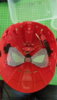
I'm attempting to upgrade a Iron Spider-Man costume I bought on 'Wish' and a Hasbro mask.

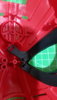
The goal is to mechanize the lenses, have the lenses glow blue, add instant kill red eyes, maybe a speaker with a few lines from 'Karen'.

For the suit I plan to add EVA foam to the armour webbing and build shoulder pads. Add lighting to the costume as well.

This is a tall order for me as I have no Cosplay or electronic engineering experience!

Your input would be much appreciated!

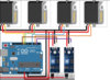
This is the Hasbro mask I have taken apart so far, I have played around with servos and an IR sensor.

The problems so far are:
- the servos don't seem to sync together when activated.
- haven't figured out how to control each lens
(what format do videos need to be in to be posted, it doesn't seem to like mp4?)

This is the code I found for a model railway crossing system:

#include <Servo.h>
int ir2 = 2;
Servo myservo1;
Servo myservo2;
void setup()
{
pinMode(ir2, INPUT);
myservo1.attach(9);
myservo2.attach(10);
}
void loop() {
myservo2.write(0);
myservo1.write(0);
if (digitalRead(ir2) == LOW)
{
myservo2.write(90); // sets the servo at 0 degree position
myservo1.write(90); // sets the servo at 0 degree position
delay(200);

}
}
 

Attachments

  • 20191230_150413.jpg
    20191230_150413.jpg
    1.1 MB · Views: 678
  • 20191230_153235.jpg
    20191230_153235.jpg
    934.6 KB · Views: 1,736
  • Screen Shot 2020-01-02 at 21.11.09 copy.jpg
    Screen Shot 2020-01-02 at 21.11.09 copy.jpg
    405.9 KB · Views: 962
Last edited:
I think most people upload a video to another site (like YouTube) and then link it here.

Without a video of what you're seeing it's hard to tell what's going wrong. From what I can see in the picture of the mask it's only using one servo, but you've got code for 2 servos, and you included a diagram for a system that uses 4 servos and some other electronics. Which of those are you trying to follow?

For the eyes, I would try RGB LEDs around the edges of the eye. You can have them glow blue normally, then change them to red and close your eye lenses as far as you can for your "kill mode" effect. I don't know if the LEDs would get in the way of the lenses, so don't commit to that without some testing, but it's how I would do it.
 
Sorry I should have explained a bit more.

I included the wiring diagram to give an idea of what I have done with 2 servos, I adapted the code for using 2 servos, which is what I'm using at the moment.

I like the idea of the RGB LED around the edges of the lenses, but I was thinking the instant kill mode has like a single red LED for the 'pupil'

I've linked a video to 1 servo controlling 1 eye which doesn't look too bad, but when I connect 2 servos to control both eyes the timing isn't great.


Attachments

  • TomHolland81919-625x352.jpg
    TomHolland81919-625x352.jpg
    21.3 KB · Views: 444
I'm hoping to start tinkering with my own Arduino here in a few days. My gut feeling is that the delay you're seeing is something that can be fixed by changing the code, but I'll need to see if I can reproduce the problem and start getting familiar with the ins-and-outs of Arduino first.

For reference, you're seeing multiple variations of the same problem:
1. Right Close, Left Close, Open Together
2. Right Close, Left Close, Right Open, Left Open

The delay between the two eyes seems like it's probably 200ms (aka: the value you told it in the code), which would make me think you've got an issue in your main loop. If you want, you could try this alternative version and see if it works better for you (only replace from "void loop()" onward):

Code:
void loop() {
    if (digitalRead(ir2) == LOW)
    {
        myservo2.write(90); // sets the servo at 0 degree position
        myservo1.write(90); // sets the servo at 0 degree position
    } else {
        myservo2.write(0);
        myservo1.write(0);
    }
    delay(200);
}
 
As for having a single light in the center of your eye while in kill mode, I would see if I can find someone else who's done the same thing. I think you're going to find it hard to implement without having a blind spot in front of your eye the entire time you're not in kill mode, as you've got the LED right there along with it's wiring. The closest I've personally seen used a single LED in the corner of each eye, rather than in the center.

Warning: Crazy R&D idea ahead. Likely won't work for you or anyone else, I just needed to get it out of my system.
I can think of a cool way to do this if you could fit two polarized filter inside the mask and have one that can be toggled/rotated. You could damage the one filter around the center, then if you toggled/rotated the other at the same time you changed your LEDs to red you'd just have a red glow at the center and black surrounding it. I don't think a face shell that already has moving lenses is a good candidate for adding additional moving parts, so you'd need a way to electronically toggle the filter. The good news is that this has been done for ages in LCD screens of all shapes and sizes. The bad news is that you'd basically be looking to make a DIY LCD screen on a concave surface, and that concave surface is likely going to mess with the effect (I've never heard of a curved LCD screen, only curved LED screens).
 
I tried your code and it seemed to sync together better, but when I changed the start and end positions to make one servo go clockwise and the other anticlockwise they went out of sync again!

This is the code I used:
#include <Servo.h>
int ir2 = 2;
Servo myservo1;
Servo myservo2;
void setup()
{
pinMode(ir2, INPUT);
myservo1.attach(9);
myservo2.attach(10);
}
void loop() {
if (digitalRead(ir2) == LOW)
{
myservo2.write(0); // sets the servo at 0 degree position
myservo1.write(90); // sets the servo at 0 degree position
} else {
myservo2.write(90);
myservo1.write(0);
}
delay(200);
}

This was the result:

could it be the power supply? I've got it hooked up to my laptop through USB connected to the UNO.

btw, I'd like to say I like your crazy idea but I have no idea what you are suggesting! lol
 
DO NOT POWER FROM THE UNO!..

you will blow your board out.

Servos can pull up to 1A under load...

Your Arduino can NOT power -anything- outside of a simple accent led.

Your -CAN- control devices.. (but that is -not- powering them)


tip:

post your code inside of [ code ] [ / code ] tags (no spaces)

makes it easier to read for the rest of us.


If there any any current issues.. post where you are at.. and I'll help if I can. :)


RE: kill-mode

I did some small kits for another member here.. that was specifically just for the red led 'pupil' (very basic)

I would imagine.. you could just route a small LED into one of the holes (I would not 'center' in.. but have it positioned more toward the 'nose' section)

* Using a clear led wouldnt make standout as much.. and if its BEHIND one of the holes.. maybe not viewable at all from the outside???

This could be triggered anyway want in the same code you are working on above.

add another button to trigger the 'kill mode'.. or whatever interaction you want really to turn it on/off
 
Lol, I had read somewhere that you could only power 1 servo with the board but as it seemed to be ok powering 4 so I thought it would be ok!

RE. Instant kill mode
I like the idea of the positioning of the LED. I was thinking to also connect a speaker for "Instant kill activated" with a switch to turn on the LED.

Looks like I have quite a bit of work to do!
 
In -theory- you can TEST with 1 servo connected to the board (still not advised).. but that should NOT be under load. (not moving/pushing/pulling anything)


As far as your 'speaker' idea.. you'd also need a way to playback an audio file. (not hard.. just more parts/codes)

I suggest using a DFPlayer mini module as they are cheap and easy to use.
 
Do you think a 2000mAh battery would be ok to power 2 servos, IR sensor, the LEDs for around the eyes and instant kill + DFPlayer mini module?
 
It should work.

Without knowing how much current all of those things together will pull... I can say for how long the battery will power things though. (my guess is long enough though)..

led and Arduino will be minimal... not clear on the DFPlayer current needs or what is uses during playback?

Servos pull most current when moving under heavy loads. this torque requirement should not be an issue IMHO..

Tip:

Do not use DELAY(); in your code.. :)

Its a code blocking function.. (meaning nothing else can work/run/fire/check while you are stuck in a delay() )

In the Arduino IDE, checkout the BlinkWithoutDelay example...

this is how you should approach ALL code.
 
This may not help you depending on if you have a timeline or not but Cavin Creations on YouTube and Instagram is working on not just a kit but also a tutorial for his mechanical lenses that he has been developing since right around Civil War coming out. I have one of his most recent versions and it is very good and smooth, thought you might be able to use that as a reference if there is something off on yours.
 
This may not help you depending on if you have a timeline or not but Cavin Creations on YouTube and Instagram is working on not just a kit but also a tutorial for his mechanical lenses that he has been developing since right around Civil War coming out. I have one of his most recent versions and it is very good and smooth, thought you might be able to use that as a reference if there is something off on yours.

Calvin's mask looks great, looking forward to his tutorial!
 
Not sure why nobody posts links?


This perhaps?


Holy cow! not cheap!


$200.00 alone for this 'shell & eye piece kit'?? Wowzers!

granted its a nice kit that is molded to hold all the electronics (not included).. and the rack/pinion (3D printed parts????)

Still need to buy all the electronics (not too bad if you buy clones off ebay I guess?))......
Also still need to by the IR modules and figure out a way to mount those..


and edit/alter your own code.

And none of the above includes the 'face skin/cover' (didnt catch where he said he bought his from?)

I can write all the code for everyone.. but a cheaper face shield/eye kit needs to b found/designed :)
 
Last edited:
Thanks for the link.

I guess the price is the cost of the R&D as well.

It looks like a great kit. I think the design is based on one of the other Hasbro toy masks I have seen. The gears are really cool! But I guess that's only gonna happen with a 3D printer.
 
I guess.. and of course hes allowed to charge whatever he feels.

Usually not everyone person pays for the R&D though! LOL.. sorta portioned out in/over the quantity..

either way end result is pretty good!! :)

**edit: I did forget about the 'motherboard' PCB he created/included.. not needed and not necessarily hard to do, but does add to the ease of use for his kit/product **

Are the main mask part(s) 3D printed? or cast? injection molding?


You'd definitely have to do some 'hacking' to add in the IR sensors.. as his kit if a 2-part faceshell/kit.. and the inner 'eye' shield, doesnt have any pre-built places to mount them.

You could probably hide the main board under the 'eye shield' piece.. and cut/extend the sensor/diodes on the end to be mounted easier on the inner eye shield portion.


Found in side list on YT vid page:
Not a BETTER face base... but includes ALL electronics and kill mode for $200


Seems to use hot glue? (not great)
Uses two nanos? (not needed..1 will work)
 
Last edited:
yeah, the parts don't look 3D printed, but I don't really know much about 3D printing.

This mechanism looks interesting, although movement isn't smooth and I'm not sure I like the idea of having flexible wires near my eyes!

 
I like the current IR sensor approach as it reacts to the eye/light reflection well.... that most people are doing

The mechanical part in the vid was not good IMHO.. :)

The Cavin one has the most 'polish' I have seen on a kit so far.. and is perfect IMHO (except for pricey for my pockets!) LOL

You have to buy your own electronics anyways.. so instead of some switches.. get some sensors...
 
I have seen this 'eye blink sensor' which I guess is some form of an IR sensor but I have not found where to purchase it, not at a reasonable cost anyway!

 
Its more or less the same thing I believe.

Some added boards to make audio blinking sounds... same sensors. Maybe is a different or custom PCB shape.

The electronic parts cost for this project are minimal.

Literally.. the most expensive parts for the build would be the servo(s).. maybe $3-5 USD each? and your battery pack. (still only several USD bucks)..

The sensors and Arduino are like dollars apiece. :)
 

Your message may be considered spam for the following reasons:

If you wish to reply despite these issues, check the box below before replying.
Be aware that malicious compliance may result in more severe penalties.
Back
Top