xl97
Master Member
good luck!
read everything in here....
(then read it again!) haha
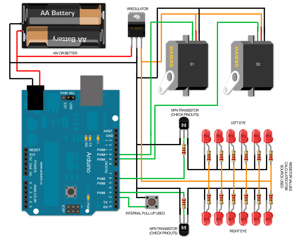
make sure you regulate the power to your servos (so you dont ruin them)..and not power them from your Arduino..
same for the led(s) (regulate the voltage/current for them).. depending on your end set-up..
connect 'ground' from Arduino and battery pack and servo's
read everything in here....
(then read it again!) haha
make sure you regulate the power to your servos (so you dont ruin them)..and not power them from your Arduino..
same for the led(s) (regulate the voltage/current for them).. depending on your end set-up..
connect 'ground' from Arduino and battery pack and servo's

") ... that the LM7805 (I think) only lets in around 800mA constant current?
... that the LM7805 (I think) only lets in around 800mA constant current?