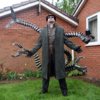
Doc Ock from 2004 Spider-Man 2 (Alfred Molina) - Pic Heavy

midge5296

New Member
First time starting a thread on here.

I recently went to Houston for Comicpalooza / Galacticon summer of 2013 and while walking around the convention floor, a Doc Ock had walked past my fiance and I. He had done the comic version and I had said to her that I was more interested in Alfred Molina's portrayal of the role and how the costume was designed. She, also being a costumer, told me she loved the character and I should do it. So began the journey.

I plan on releasing the finished product at New York Comicon 2013 (NYCC).

I hope I can finish in time!!! Wish me luck.
 

Attachments

  • doc-ock.jpg
    doc-ock.jpg
    44.7 KB · Views: 10,445
Last edited:
Looking forward to some villains to counter the rising number of spider-men on this forum.
 
xfhgBzp.jpg

After I was happy adjusting the size, I printed the files out and used an exacto knife to cut the stencils.
 
aKUgy5U.jpgygRdPuN.jpg

I made a second copy and used regular scotch tape to connect them together to get an idea of the size I am going to be dealing with. In the one photo you can see a tape measure to see the scale.
 
Now that the stencils were done I had to figure out what materials to use and how much of it I needed. Each arm segment would have 24 vertebrae segments (totaling 96) with a hose in the core containing all armature wiring, electrical wiring, and lines to allow for pincer manipulation. It would also have tubing near the rounded points of the triangle for added support and stability. Here is a break down of the arm materials:

2 sets of 4 - 24" x 24" x 9/16th" Extra Thick Multi-Purpose Foam Floor Mats
30' x 1-1/2" Poolmaster 33430 Premium Vacuum Hose
100' x 1/2" Raindrip Poly Hose
50' 11-1/2 Gauge Armature Sculpture Wire
50' 24 Gauge Black Stranded Hook-Up Wire
50' 24 Gauge Red Stranded Hook-Up Wire
15' Bicycle Brake Cable and Housing Kit
6 1-1/2" Flat Hinges
12 1-1/2" Springs
8" x 10-1/2" Red Transparent PVC Film
16 5mm LED White 10,000 mcd (mcd is a brightness category. 7000 is a standard LED, so this is slightly brighter)
4 9v battery with connector (I know that the working load is 5v for the LEDs but it can still handle a 9v load without an issue plus it gives you a longer run life)
2 cans of spray plasti-dip
2 cans of spray paint primer
2 cans of spray paint silver
1 can of spray paint yellow for highlights

I'll add to the list in a later post to discuss how the back harness is made and how I fasten the arms to the back harness.

- - - Updated - - -

I tend to lean towards the villains. Everyone loves a misunderstood person. LOL!!
Looking forward to some villains to counter the rising number of spider-men on this forum.
 
You certainly aren't holding back on this suit! Subscribed to see what else you come up with.
 
View attachment 227979View attachment 227980View attachment 227981View attachment 227982View attachment 227983
Once the stencils was made it was time to mark out the foam matting. I tried to arrange the pattern to fit the most on there. I managed to get 12 per sheet.
Now that the foam was all marked out it was time to start cutting (...Lots and lots of cutting). I started first by using a regular Xacto knife. What a mistake. This foam is too thick to have clean pieces. Save yourself time. Only use it for detailing. I bought a hot knife. Think of it as an Xacto knife with a soldering iron. Cuts through clean and easy. Best $30.00 I spent. I have also seen a belt saw used but I didn't want to spend that kind of money.

I sectioned out the large foam to make it easier to handle. First was the outline of all the rounded triangles. Next was the large inner circle. Then the three smaller outer circles. All 96 triangle segments! I tested my cool and took my time. The circles don't have to be perfect but I tried to make it look good. The more snug the holes are on the hose the less adhesive I'll need later. (more on that in a bit)

- - - Updated - - -

TiRJVUv.jpg4IOQemD.jpgcywrcdM.jpg
One down... 95 to go....

On a side note, The triangles are wider at the base. I marked which side is the base with a small little dot. It will save headaches arranging things later.
 
Last edited:
u3mqfqq.jpg LvbmGqu.jpg t7BlOEv.jpg

Now that all of the arm vertebrae are cut out its time for the pincer segments. There are three main parts. The center that all "fingers" of the segments attach to, the main part of the "finger" section and the tip of the pincer. Each segment has multiple layers so that it has a little volume to it and not just a flat piece.

I know some people will see the reference photo and may comment that the top 2 and bottom 2 arms have different pincers. I didn't change that. I wanted something more uniform. In the future this may change but for now that's how I did it.
 
tATFZKc.jpgTENONVa.jpgIxpzh7j.jpg

Each segment for each finger were cut out. Three fingers per arm x 4 arms. I added a thicker under layer to the main 6 sided segment to give a little more support and size.
 
I'm totally subscribing to this, coming along nicely. So how articulated are you planning these arems to be?
 
Very ambitious and exciting project. Looking forward to watching this come together.

Keep up the great work!
 
I'm totally subscribing to this, coming along nicely. So how articulated are you planning these arems to be?

The arms will be position-able but it has to be done manually. There is no mechanics planned as of yet. The top 2 pincers will be able to open and close through a spring and wire system. All 4 arms will have LEDs in the pincers as well with a battery system.

Thanks for the interest.
 
Back
Top