Death Trooper E-11D Field Marshal Build

DrtyJerzTrooper

Member
RPF PREMIUM MEMBER
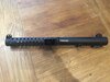
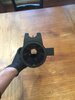
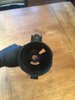
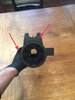
Hey Guys, I have been working on my DT (close to completion) for some time...but the one thing I have gotten really good at lately has been building the E-11D using Field Marshal’s parts. I have made 5 of these so far...learning as I go and improving small components here and there. I haven’t seen anyone post how to build these yet and as I build more I’m open to suggestions on how to make it even better.

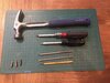
I have a few more coming in from folks who want me to build theirs so I will show how they are taken apart, what I save, where to cut weight (if you’re going to troop with it), some different engineering decisions to be made, etc.... Feel free to chime in and provide feedback.

I also need to acknowledge two people upfront in all this....Frist is Chris (aka Field Marshal) who builds these incredible parts, without him none of this would be possible. Second is my bud Henry (I forget his TK but he is a GML in the Canadian Garrisson), he is a wealth of knowledge from reference material...it’s really amazing how much he knows.
 
So....here is what we start with a Airsoft Sterling from Evike.

S&T / Beta Project Full Steel WWII Sterling L2A1 Airsoft AEG Submachine Gun

The whole thing needs to be gutted and stripped before we do anything else. You will need a few tools to do this. I use a screwdriver with removable tips, a metal punch, hammer, etc.

When I’m done this will be completely stripped down so we can cut the greblie holes, grind the sights, cut the barrel, and get it read for painting.

I also recommend getting aome kind of storage solution to house all the parts...both the ones that come off the Sterling as you will need them as well as keeping track of the parts from Chris as these are small and can be confused with other parts and/or lost very easily.

I purchased some HDX boxes from the Big Orange home improvement center....anything will do, don’t get fancy....just needs to hold the parts so they don’t get lost. I think I paid $15 for 4. So they are cheap.
 

Attachments

  • 011D4105-8DEF-4085-9409-3BFA6D31851A.jpeg
    011D4105-8DEF-4085-9409-3BFA6D31851A.jpeg
    2 MB · Views: 261
  • 5BB754F4-6376-4BE3-8031-36E790D06692.jpeg
    5BB754F4-6376-4BE3-8031-36E790D06692.jpeg
    1.7 MB · Views: 168
  • 1A49C2A8-4DB2-470D-937C-5ECBBD2572CB.jpeg
    1A49C2A8-4DB2-470D-937C-5ECBBD2572CB.jpeg
    2.1 MB · Views: 375
  • 359F4502-69F0-4C50-ABB6-BC4566CCD088.jpeg
    359F4502-69F0-4C50-ABB6-BC4566CCD088.jpeg
    2.7 MB · Views: 328
  • 6548C5F1-B8A3-4B04-9994-C229267B74FD.jpeg
    6548C5F1-B8A3-4B04-9994-C229267B74FD.jpeg
    1.9 MB · Views: 228
  • 0F0A63D5-242C-4EBE-919D-A8024916AA96.jpeg
    0F0A63D5-242C-4EBE-919D-A8024916AA96.jpeg
    1.4 MB · Views: 222
Last edited:
Let’s start the dissassembly!

1. I take the folding stock off first. It’s a pain to deal with because if it’s not secured on the barrel it flops all around and is super annoying. Plus the inner Airsoft piston need to come out the back and it can’t be removed without taking the stock off first.

2. I take the rear wnd cap off next because it’s easy and I’m already back there.

3. We need to remove the spring and housing that sits behind the piston it is in the back under the end cap. You will need to remove all the screws. Careful removing this piece as it’s spring loaded and can fly out...you won’t be replacing it but just make sure it doesn’t smack you square in the face.

4. Next you can remove the charging handle and ejection port cover. Twist the charging handle about 1/2 turn and it will pop off....slide the metal charging handle cover out the back of the Sterling.
 

Attachments

  • D0D57BD1-4980-4A58-B186-CB288FC3B93E.jpeg
    D0D57BD1-4980-4A58-B186-CB288FC3B93E.jpeg
    1.5 MB · Views: 198
  • 3B8DAD6A-B8EF-45BD-85C0-EBD72B7921F0.jpeg
    3B8DAD6A-B8EF-45BD-85C0-EBD72B7921F0.jpeg
    909.7 KB · Views: 200
  • 265B4E1A-A9B5-4DC7-9C8D-E1151A762003.jpeg
    265B4E1A-A9B5-4DC7-9C8D-E1151A762003.jpeg
    687.2 KB · Views: 209
  • 5696093B-B519-48C6-BF8F-BE0C282B786E.jpeg
    5696093B-B519-48C6-BF8F-BE0C282B786E.jpeg
    1.4 MB · Views: 223
  • 679124CB-CD31-4C27-A346-6CDDA2073532.jpeg
    679124CB-CD31-4C27-A346-6CDDA2073532.jpeg
    1.6 MB · Views: 200
  • 572B3FC3-BC08-41BD-B284-6BE74A4361D6.jpeg
    572B3FC3-BC08-41BD-B284-6BE74A4361D6.jpeg
    2.3 MB · Views: 200
  • 391DF26C-75ED-4204-B6D7-B0080A8BF87F.jpeg
    391DF26C-75ED-4204-B6D7-B0080A8BF87F.jpeg
    2 MB · Views: 209
The next parts of the dissassembly are tricky so will have to walk everyone through this more detailed.

1. Remove the pistol grip...2 screws....slides right off super easy.

2. Next are the two covers that keep the selector switch and the wires for the existing motor covered. They are connected with 1 hex head screw and 2 Phillips screws on either side. The selector switch was in fact removed on the hero prop but we will leave it attached for now. Once these are removed we can go about removing the trigger assembly and piston. Make sure to save the pieces together. The selector switch has a small spring on the inside.

3. Remove the Hex head screw on the underside of the barrel. This is what connects the piston to the hop up....you will need some extra room to remove the trigger assembly. This allows the trigger and piston (still connected to slide around a bit). You also will need to remove the single Phillips head screw that connects the piston to the hop up along with the washer, on the inside of the barrel. Careful....this screw is small.

4. Now with this removed you can maneuver the trigger assembly to disconnect it. There is a roll pin towards the back that you will need the metal punch to get rid of. Pop that sucker out and you’re halfway there. The trigger assembly is also secured by a small plastic piece that connects from the inside of the piston to the inside of the gears of the trigger. You will need the metal punch again to slide this out of the way to pop off the lower trigger assembly as well as guide the pistion out the back of the Sterling.
 

Attachments

  • 7135B1DC-DCAF-4ACB-A955-8671561951F0.jpeg
    7135B1DC-DCAF-4ACB-A955-8671561951F0.jpeg
    1.7 MB · Views: 228
  • 4323B966-0EA5-4B4A-8966-B4A2248BC17E.jpeg
    4323B966-0EA5-4B4A-8966-B4A2248BC17E.jpeg
    1.2 MB · Views: 189
  • 112141EA-417C-4BA7-B5CF-58E41AE565EE.jpeg
    112141EA-417C-4BA7-B5CF-58E41AE565EE.jpeg
    1.6 MB · Views: 193
  • 532D30D3-C5AB-43CD-8263-C9BE177298AD.jpeg
    532D30D3-C5AB-43CD-8263-C9BE177298AD.jpeg
    1.6 MB · Views: 194
  • 1393C27F-B7C1-427D-9D9F-50C39812B457.jpeg
    1393C27F-B7C1-427D-9D9F-50C39812B457.jpeg
    1.5 MB · Views: 196
  • 3CFE00F6-2693-43FF-B8C6-1E0EF70F34A9.jpeg
    3CFE00F6-2693-43FF-B8C6-1E0EF70F34A9.jpeg
    1.6 MB · Views: 187
  • E84779A0-E77F-4EA5-8E3A-51FB39A3CC0A.jpeg
    E84779A0-E77F-4EA5-8E3A-51FB39A3CC0A.jpeg
    1.2 MB · Views: 196
  • FFB23F5E-A66B-413D-8F37-58683E48DC31.jpeg
    FFB23F5E-A66B-413D-8F37-58683E48DC31.jpeg
    742.1 KB · Views: 189
  • 5693F66C-AEDF-4364-90A8-0ABB733C52C7.jpeg
    5693F66C-AEDF-4364-90A8-0ABB733C52C7.jpeg
    835.1 KB · Views: 203
  • F7799DE1-D37F-485B-93CB-D9C6C1861FFB.jpeg
    F7799DE1-D37F-485B-93CB-D9C6C1861FFB.jpeg
    1.1 MB · Views: 202
  • E438AC89-0453-4F5E-93E1-851F4C67AD4C.jpeg
    E438AC89-0453-4F5E-93E1-851F4C67AD4C.jpeg
    992.6 KB · Views: 202
  • 056D54E5-F65C-4406-A361-24DD8579716A.jpeg
    056D54E5-F65C-4406-A361-24DD8579716A.jpeg
    875.1 KB · Views: 192
Last edited:
We are in the home stretch. Everything slides out the back of the Sterling....the muzzle cap is the ONLY thing attached with hex screws that can be removed from the front. Now that you gave the piston out and the trigger assembly we can focus our attention to the front of the Sterling.

1. Now that the trigger and piston are removed you can remove the barrel and hop up out the back of the Sterling. You can also remove the plastic hop up piece on the inside of the magazine well.

2. You will need to remove the front muzzle cap which could be all orange or black with a rubber orange tip. This piece is a pain to remove mostly because the screws are on super tight.

3. Next is the bayonet lug that has to be removed from the inside of the barrel. It is secured by a small Phillips head screw, which will allow the barrel support to fall out the back.

You are then left with a clean Sterling ready to go! Next I will tackle cutting up the barrel to support the barrel shroud.
 

Attachments

  • 7BB05167-3D5A-4DBE-B1C7-A5C76DAF4283.jpeg
    7BB05167-3D5A-4DBE-B1C7-A5C76DAF4283.jpeg
    489.6 KB · Views: 191
  • D56972BD-8EB0-474B-B065-1EEDC58B88C2.jpeg
    D56972BD-8EB0-474B-B065-1EEDC58B88C2.jpeg
    513 KB · Views: 177
  • 6BB0D43B-632A-4DBC-B4C1-562B35FFD583.jpeg
    6BB0D43B-632A-4DBC-B4C1-562B35FFD583.jpeg
    598.1 KB · Views: 200
  • 27E84D4D-9E41-4ACA-8289-76E12E64E84C.jpeg
    27E84D4D-9E41-4ACA-8289-76E12E64E84C.jpeg
    788.3 KB · Views: 198
  • D0F33D3A-2AE4-4B83-AEBA-F82D33EA833B.jpeg
    D0F33D3A-2AE4-4B83-AEBA-F82D33EA833B.jpeg
    850.7 KB · Views: 179
  • F14785A3-6D58-4B17-8CF0-A4B5A72F9B00.jpeg
    F14785A3-6D58-4B17-8CF0-A4B5A72F9B00.jpeg
    812.4 KB · Views: 171
  • 838E3090-4208-4723-96B8-C5E7B1F602F6.jpeg
    838E3090-4208-4723-96B8-C5E7B1F602F6.jpeg
    831.9 KB · Views: 186
  • 3A60D585-5E71-4AE4-9EF2-6DA80F050F2E.jpeg
    3A60D585-5E71-4AE4-9EF2-6DA80F050F2E.jpeg
    855.2 KB · Views: 131
  • 87BC5D83-5861-4C59-A064-19F9511F05D8.jpeg
    87BC5D83-5861-4C59-A064-19F9511F05D8.jpeg
    551.2 KB · Views: 178
  • FF04162D-7B06-448E-A26E-74160B4AFA5D.jpeg
    FF04162D-7B06-448E-A26E-74160B4AFA5D.jpeg
    480.9 KB · Views: 139
  • 16548BE7-3952-41A2-94F5-7061661D8003.jpeg
    16548BE7-3952-41A2-94F5-7061661D8003.jpeg
    663 KB · Views: 216
So now that we have a fully disassembled we can begin to cut this sucker up. The hand guard and the outer piece of the iron sights can be removed with Pliers as shown with the red arrows. You could cut them in half with a Dremel but they pull off easy as they are only tack welded on. The other thing you will need to do if you use my method is to grind the top part of the sights off as shown.

IF you want to use the delrin from Chris, that is kosher too....I can help there, just comment in the thread and I can guide you.

The next part is where Chris and I differ on barrel shroud attachment methods. His method is just as secure as mine however my method allows for more of the Sterling barrel to remain to support the outer barrel shroud. Chris sells a solid piece of delrin which screws into the hop up and allows you to screw into the delrin. It also requires you to cut 4 inches off the front of the barrrel of the Sterling. I like to keep the full length of the orginial barrel for extra support. I do not use the delrin and I also cut the hop up in half....mostly these are build for trooping and reducing weight is my primary goal. So the 13 inch barrel shroud extension is only a 6 inch extension using my method vs a 10 inch extension using the delrin piece.

I then slide the barrel shroud over the clean barrel and cut “slits” so the holes are clean you can see straight through the side holes. I use a Dremel to cut the barrel so it fits properly then hand file the areas so they are clean. You can see how the barrel shroud covers the barrel but the slits allow the holes in the shroud to be see-through.

Lastly, I JB Weld the holes that line up with the barrel shroud screws so they are easier to attach later. I would recommend using some painters tape on the inside of the barrel to keep the JB Weld smooth on the inner barrel....because trying to sand that will be a pain. I also JB Weld the iron sights I grinned down. You won’t see it, but I like to keep all parts clean.....even the ones you don’t see. Once the JB Weld is dry you will want to drill and tap these holes with a 6/32 bit.
 

Attachments

  • 92B4442C-B346-44A8-97D0-CEEF2CC33643.jpeg
    92B4442C-B346-44A8-97D0-CEEF2CC33643.jpeg
    513.2 KB · Views: 194
  • 875BE0EC-4F54-4975-BB71-E483277787CD.jpeg
    875BE0EC-4F54-4975-BB71-E483277787CD.jpeg
    256.3 KB · Views: 190
  • F51B7409-03C4-4C45-925E-388521543848.jpeg
    F51B7409-03C4-4C45-925E-388521543848.jpeg
    240.8 KB · Views: 194
  • 0183E8AB-B9BB-4708-8D1A-FC188BBEDD7C.jpeg
    0183E8AB-B9BB-4708-8D1A-FC188BBEDD7C.jpeg
    196.4 KB · Views: 200
  • C7707E7A-A22C-419F-B99F-F7D7C90A0D1D.jpeg
    C7707E7A-A22C-419F-B99F-F7D7C90A0D1D.jpeg
    242 KB · Views: 185
  • 07061A96-EA3E-4526-95C4-B2EA0D0C37C6.jpeg
    07061A96-EA3E-4526-95C4-B2EA0D0C37C6.jpeg
    91.1 KB · Views: 196
  • 7B77A535-2EA4-41D0-880D-223513EBC53D.jpeg
    7B77A535-2EA4-41D0-880D-223513EBC53D.jpeg
    263.2 KB · Views: 213
  • 17438F0B-6BD6-4D0F-BDB8-2F5ACEF8BB5E.jpeg
    17438F0B-6BD6-4D0F-BDB8-2F5ACEF8BB5E.jpeg
    683.3 KB · Views: 199
  • 9F38F3B6-B2FB-49AB-B69B-DBD88E14F1CC.jpeg
    9F38F3B6-B2FB-49AB-B69B-DBD88E14F1CC.jpeg
    621.2 KB · Views: 199
  • C4040425-2FAB-4C64-9E97-068B31C6E09E.jpeg
    C4040425-2FAB-4C64-9E97-068B31C6E09E.jpeg
    163.1 KB · Views: 174
  • 8B75B22C-602D-4DC4-BE49-68C54DD52030.jpeg
    8B75B22C-602D-4DC4-BE49-68C54DD52030.jpeg
    785.5 KB · Views: 175
Last edited:
Two other things I recommend doing to the barrel assuming you keep the full length is....

1. grinding the front opposite the side with the magazine. When you attach the rail system there is a small lip on the end of the Sterling that will cause the backing piece to sit off a bit. You can hand file or grind it down with a Dremel like I did. You can see how the left side of the barrel is thinner compared to the right side.

2. You will need to enlarge the hole on the bottom of the barrel closest to the tip. This is done because the worm screw for the laser will contact with the barrel and will “push” the barrel away causing a stress point.
 

Attachments

  • 03732A5C-3004-41A2-8B6F-C9629CBB301D.jpeg
    03732A5C-3004-41A2-8B6F-C9629CBB301D.jpeg
    389.8 KB · Views: 180
  • 3489477D-43C3-4E4A-8DE5-B6C50AF720B3.jpeg
    3489477D-43C3-4E4A-8DE5-B6C50AF720B3.jpeg
    627.4 KB · Views: 185
Ok, let’s talk about reducing weight for a few minutes. This thing is pretty heavy as it is without extra weight. My general recommendations are you do the following.

1. Completely gut the Airsoft piston, I’ll explain how to do that in the next post but you can see the overall weight difference between the gutted vs non-gutted piston. It makes a huge difference in weight and also allows more room for wiring and/or electronics if you are so inclined.

2. Totally gut the trigger assembly, same thing with the piston. There is a significant amount of weight you can cut out here and you don’t need all the gears, bearings and washers in the trigger assembly.

3. Lastly is the hoop up and this is a toss up depending if you decided to use the piece of delrin from Chris without my method previously or with my method (which you will need to sand down the delrin so it’s perfectly smooth all around to fit down the barrel without cutting it off completely.). Cutting the hop up in half will also allow more weight reduction. I also plugged up the hole with some JB Weld so there isn’t any LED leak out the front of the barrel but if you do or don’t do this is your choice.
 

Attachments

  • DC72CEE9-B1D4-40D7-8E72-506ABD4E5DA1.jpeg
    DC72CEE9-B1D4-40D7-8E72-506ABD4E5DA1.jpeg
    2 MB · Views: 189
  • 9B8BC733-3EFB-4136-929A-AB398ACF7389.png
    9B8BC733-3EFB-4136-929A-AB398ACF7389.png
    5.2 MB · Views: 161
  • 4E854CDA-1681-4B8C-8F00-8AD53D1C5586.jpeg
    4E854CDA-1681-4B8C-8F00-8AD53D1C5586.jpeg
    2 MB · Views: 161
  • 238D3103-FD0B-4CC2-A15D-59F4C9148939.png
    238D3103-FD0B-4CC2-A15D-59F4C9148939.png
    4.1 MB · Views: 181
  • E976698E-D62F-4D93-894B-83F60ADD2F64.png
    E976698E-D62F-4D93-894B-83F60ADD2F64.png
    3.5 MB · Views: 153
  • 67F23094-0927-48E0-9DEE-16D8CDDEE70F.png
    67F23094-0927-48E0-9DEE-16D8CDDEE70F.png
    2.5 MB · Views: 168

Your message may be considered spam for the following reasons:

If you wish to reply despite these issues, check the box below before replying.
Be aware that malicious compliance may result in more severe penalties.
Back
Top