Daft Punk Thomas Helmet -- Skipped a few chapters

...after consulting with Volpin and other considerations, I opted to add 2 x 30 mm fans to my helmet. I'm still waiting for the voltage regulator, but they're in.

I had also received my 2nd bucket from Volpin to give it another stab at chroming. While talking to the owner of Coat of Chrome, he mentioned that he had a fix and if I was interested in sending the already chromed bucket back to him for re-chroming. "RE-CHROMING!!??" I asked :confused.
He said, "yeah...." 1 week later (minus transit time), I got my helmet re-chromed with much better results.

6164288601_2f095ffb12.jpg


Props to Don at Coat of Chrome as he did the re-chroming free of charge.

:love
 
Last edited:
so now that a couple of you guys have finished your daft buckets with the thomas LED displays working, i wonder how long until one of you starts in on a full Guy Man LED display it seems like you folk have the concept down pat now, its only a matter of time i suppose.

everytime i look up on here, i find a new person making me feel like a chump. damn you peoples and your amazing works of art. one day, I'll join your ranks.
 
so now that a couple of you guys have finished your daft buckets with the thomas LED displays working, i wonder how long until one of you starts in on a full Guy Man LED display it seems like you folk have the concept down pat now, its only a matter of time i suppose.

every time i look up on here, i find a new person making me feel like a chump. damn you peoples and your amazing works of art. one day, I'll join your ranks.

I swear I'm still working on mine, honest!

I had to move for work, massive work project(s) I've been scrambling on, etc etc etc and the usual excuses.

I hoping this weekend I will finally be able to get my office/workspace in order and get started on my next solder task: cheek EQ's.

Of course, the folks at Arduino had to go an release news of an ARM based arduino. Long of the short, it's like the dream platform for my main control board. It means I wouldn't/shouldn't have to have two arduinos like I do now to handle the work load. Integrating my code bases, simplifying communication, decreasing data traffic, reducing components, increasing expandability, better futureproofing, and all that wonderful stuff. Here's hoping it's kittens and rainbows.

I return you to your regularly scheduled thread.
 
Jeeeeze, those helmets are absolutely beautiful. You have no idea how envious I am, Guy-Man's helmet is my dream prop, and you did them both justice. Great work!
 
Well, Youtube was fast in blocking my video due to Copyright violation.. :thumbsdown


Oh well, I had to re-do it with proper non-copyrighted material.
 
on the arduino nano, what pins did you replace with angled headers?

I got rid of ALL of the straight pins only replaced the ones shown below plus ANALOG 0,1,and 2. If you see a line going in or out of the arduino, then I placed an angle male header connector.

5629675119_75f35dd2ce_o.jpg
 
Thanks man, I don't completely understand all this electronics stuff. Your work on this helmet is amazing! I've read over this thread atleast ten times before starting this project, but could you tell me again what you used those analog pins for? Was it for the light panels on the side?

Also, what is this connected in the bottom left of the picture, is it an inline voltage regulator?
http://farm3.static.flickr.com/2754/5845125133_59a2438314.jpg
 
could you tell me again what you used those analog pins for?
First let me say that I didn't need all 3 analog pins (I just needed 1). I just happen to solder those 3 for ease of soldering.

The reason why I needed an anlog pin available is becuase I'm using a potentiometer to select specific sequences, so this is the analog pin that reads that potentiometer value.

Now, if you are using the code that I posted here and that's what you have uploaded into your arduino, then you don't need ANY analog pins as that code is set to run through all 14 patterns sequentially. So it's a 'hands free operation'.

Also, what is this connected in the bottom left of the picture, is it an inline voltage regulator?
http://farm3.static.flickr.com/2754/5845125133_59a2438314.jpg

No. It's not a voltage regulator. It's just a home made power distribution strip made out of prototype board and double hangle headers with all of the row of pins connected to each other.
I used this for my Guy helmet as well. In that project I had 9 items that needed power. So, instead of making a lot of 'Y' harnesses, I just made this little power strip.
 
It's just a home made power distribution strip made out of prototype board and double hangle headers with all of the row of pins connected to each other.
I used this for my Guy helmet as well. In that project I had 9 items that needed power. So, instead of making a lot of 'Y' harnesses, I just made this little power strip.

Sorry, I really don't know that much about circuitry. Do you have any pictures of the front and back of the power distribution strip or some kind of schematics?
 
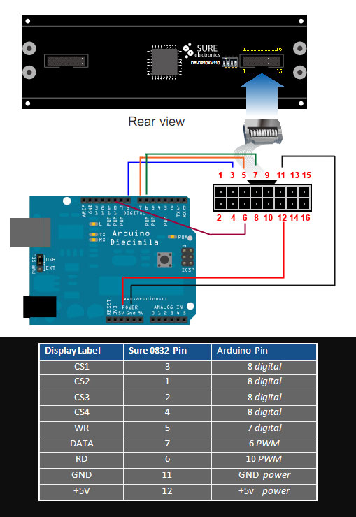
The new sure electronics 3208 3mm red matrix have the HT1632C chip.

I don't know if anyone is still trying to follow these directions, but I didn't realize it until it arrived on my doorstep.

After a few hours of playing around with a couple other libraries, I was able to edit the code for the HT1632C, but it should also work with the HT1632 also.
http://dl.dropbox.com/u/15496619/FINISHED.zip


Thanks!! Believe it or not. I recently received a new unit with the HT1632C chip and didn't work with my old code. I didn't bother to look into it, but I'll try your code tonight and if it works, you have saved me!!
 
Thanks!! Believe it or not. I recently received a new unit with the HT1632C chip and didn't work with my old code. I didn't bother to look into it, but I'll try your code tonight and if it works, you have saved me!!

if you have problems with the code only showing on the top line of the matrix, i unplugged it and plugged it back in and it fixed the problem. I added a couple other text animations that I was going to use, but when I was trying to cut the panels off the chip like you described, I ended up cutting off a few resistors :angry.
IMG_20111102_182605.jpg


What are the chances of it still working? Should I just order another? Have you come up with a better way then hacking it off with the blade?
 
Well, apparently I don't know the difference between a 5mm and 3mm LED. :confused

It seems like the board I originally had was a 5mm board making it longer than the new 3mm LED board I received. Along with that, there has been an upgrade on the chip.

To summarize:

  • Seems like SureElectronics has upgraded their chip from HT1632 to HT1632C. If you get a new board, use Andyval's code. If you have the old chip board, then use my code.
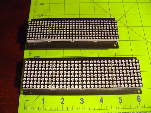
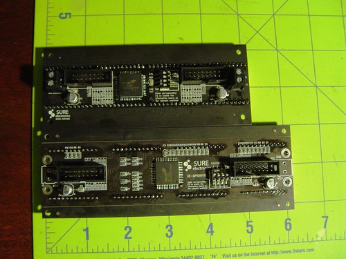
  • There is a 5mm and 3mm board available with the 3mm (top) being the shorter one of the two shown below

    6307193175_d32c694cef.jpg
6307193357_d2d264c2a1.jpg


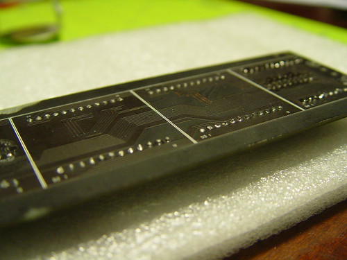
  • The 3mm board is a better fit for the helmet (space saver), but it has some resistors between the LED panel and the actual board increasing the risk of damaging the components as you saw the connectors to detach the panels. A better approach for detaching the panels is to desolder the panels using a desoldering pump or braid. Painful? Yes, but a sure way to avoid damaging components.
  • The old 5mm board has all of the components on the opposite side making it safe to use a saw to cut the panels. However, the board is longer.
    5827286132_64d8d0c761.jpg
 
Last edited:
Back
Top