Re: Daft Punk Helmet Build
I really hope they tour when the new TRON album comes out. I'd like to walk into the crowd wearing my helmet to see what happens...
On topic, I didn't get a chance to try making the new ear puck, but I DID finalize my PCBs. Thats right, electronics planning is DONE (with the small exception of the controller board, which I haven't started on yet... I have about 3 days to do that but I wanted to knock these out first)
Ok, here's how this works. The Arduino sends out signal to all of these boards, and the LEDs draw through a series of 2n2222 transistors from a series of 9v batteries. Four 9Vs will power the helmet as well as the logic board.
The Arduino goes directly to the "Shift Register" board, which houses the IC chips that take the 3 digital output channels and convert them to 32 channels of control. Size: 1.2" x 2.2"
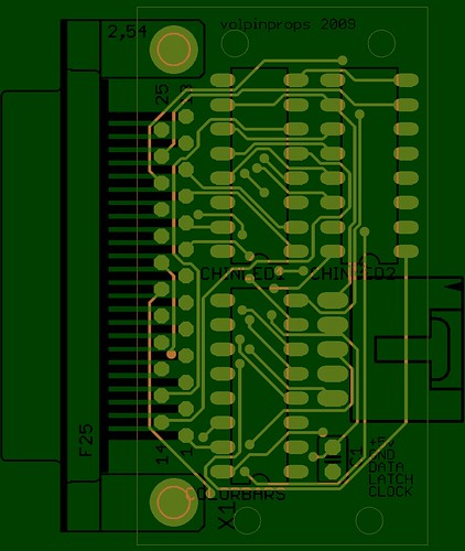
A DB25 cable carries the signal, while a 2-wire connector from the 9V supply carries power up from this control box to the helmet itself. The logic board, 9V batteries, and the board above will be placed elsewhere on the wearer (likely a jacket pocket) to make changing batteries easier, as well as free up much needed space in the helmet. The DB25 and power terminate at the "signal switching" board. Size: 1.2" x 2.55"
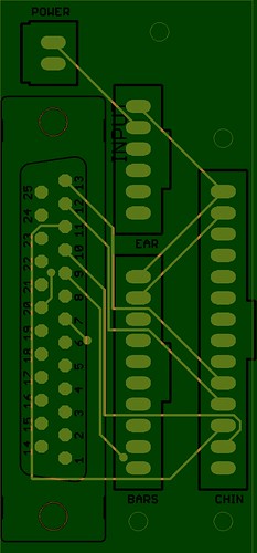
There are 3 plugs on here which take the DB25 signal and send it out to various other boards. The 14-pin connector goes to the "Chin Transistor" board, the 8-pin feeds the "color bars" boards, and the 6-pin supplies the "ear transistor" board with power. Both the ear and chin boards have their transistors housed on more distribution block boards, while the color bar boards all house their transistors on the boards themselves.
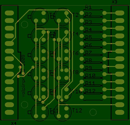
Chin Transistor board - 1.70" x 1.5"
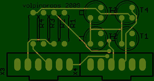
Ear Transistor board - 1.4" x 0.7"
Color bar LED boards - 2.6" x 0.4"

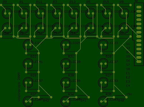
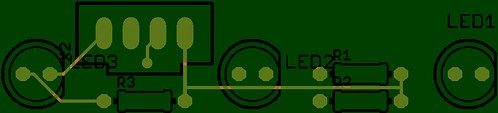
Chin LED boards - 3.45" x 2.5"
Ear LED boards - 1.9" x 0.4"
Order went in today at www.batchpcb.com so hopefully I can have these in-hand in 3 weeks and start on my crazy soldering.
These boards are only showing the top copper layer and silkscreen for preview purposes. If anyone's curious, I'm designing these boards in CADSoft's EAGLE PCB layout program. Maybe not the most intuitive program in the world, but definitely a very powerful tool.
I think you and I are the only ones who would notice, not even daft punk themselves :lol
I really hope they tour when the new TRON album comes out. I'd like to walk into the crowd wearing my helmet to see what happens...
On topic, I didn't get a chance to try making the new ear puck, but I DID finalize my PCBs. Thats right, electronics planning is DONE (with the small exception of the controller board, which I haven't started on yet... I have about 3 days to do that but I wanted to knock these out first)
Ok, here's how this works. The Arduino sends out signal to all of these boards, and the LEDs draw through a series of 2n2222 transistors from a series of 9v batteries. Four 9Vs will power the helmet as well as the logic board.
The Arduino goes directly to the "Shift Register" board, which houses the IC chips that take the 3 digital output channels and convert them to 32 channels of control. Size: 1.2" x 2.2"
A DB25 cable carries the signal, while a 2-wire connector from the 9V supply carries power up from this control box to the helmet itself. The logic board, 9V batteries, and the board above will be placed elsewhere on the wearer (likely a jacket pocket) to make changing batteries easier, as well as free up much needed space in the helmet. The DB25 and power terminate at the "signal switching" board. Size: 1.2" x 2.55"
There are 3 plugs on here which take the DB25 signal and send it out to various other boards. The 14-pin connector goes to the "Chin Transistor" board, the 8-pin feeds the "color bars" boards, and the 6-pin supplies the "ear transistor" board with power. Both the ear and chin boards have their transistors housed on more distribution block boards, while the color bar boards all house their transistors on the boards themselves.
Chin Transistor board - 1.70" x 1.5"
Ear Transistor board - 1.4" x 0.7"
Color bar LED boards - 2.6" x 0.4"
Chin LED boards - 3.45" x 2.5"
Ear LED boards - 1.9" x 0.4"
Order went in today at www.batchpcb.com so hopefully I can have these in-hand in 3 weeks and start on my crazy soldering.
These boards are only showing the top copper layer and silkscreen for preview purposes. If anyone's curious, I'm designing these boards in CADSoft's EAGLE PCB layout program. Maybe not the most intuitive program in the world, but definitely a very powerful tool.