Costume electronics

GlennTech

Active Member
Foreword

Quote: You can't leave something behind you, if you loved it.

I pulled the plug out of all my previous threads. Sorry STEALTH for been rude and sorry community to delete all my files. I also deleted the master files which I had. Sad but lets leave it alone.
I hope you guys grant me a fresh start. This time I don't associate me with costume building. Now I'll be more focussing on electronics. Since this is a huge time consumption of my life. I'm an electronic student and worked on other electronic projects in the past. So I've a bit background in the electronics world.

I want to cover various problems when been at a event that could easily be solved by using 'smart' electronic circuits.
This thread is divide in several chapters. Since I'm working on my Senior Paper for my last year of school I'll also cover technical knowledge to it. So other electronic hobbyists can guide me or can help making things simpler.
The technical content is written in Italic. Just ingnore it if you don't understand it.

Speech Amplifier Circuit (S.A.C.)

Oh man I still remember my first day on a cosplay convention. I was wearing a Halo 3 peped costume (first pep costume I've ever made). The helmet I was wearing was TOO much padded. I couldn't understand the people which I was having a conversation nor did they understand me...
Some people solves this mechanical (drilling a few holes around the ear). But that would take away the looks and accuracy.
Stormtrooper's have already a solution using 2 way headsets that are modified and other things. I wanted something 'original' something that was very versatile and economic!

This circuit is originally from
Speech amplifier circuit.
speech-amplifier-circuit.JPG


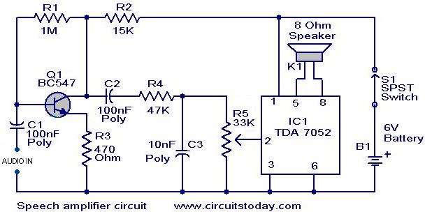
You'll need two of these. One for outside sound to your ears and one for your voice to the outside. This circuit pick ups your voice and amplify it to the outside. Very good for crowded places. After all the analysing is done through-hole PCBs will come available and also SMD PCBs.

Something I learned after using many circuits is test them before using!

I study at a school with many components. Problem is: the components aren't organised. I used values that were about the same as the original components used on the schematic.

Analysing

The circuit can be divided into 3 huge parts; Pre-amplify, RC-circuit (Low Pass Filter), final amplify stage to sound.

Pre-amplify

pre-amplify.jpg

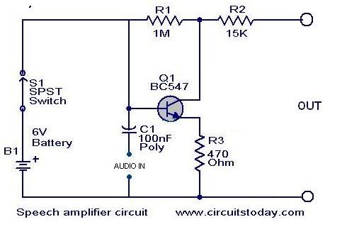
The schematic uses a BC547 (datasheet). Since the voltage produced by speaking is very low we'll want a pre-amplification. The transistor is connected as a Common Emitter Configuration. The pro's of a Common Emitter Configuration are: voltage amplify, current amplify, power amplify, average input impedance, average output impedance, very common used.
The C1 capacitor (bipolar) is used to block the direct current (you want produce DC when speaking but it's better to prevent then heal the damage)
There's also a voltage divider as you can see they used a high ohms resistor and a average ohms resistor. I'm still analysing why they did it I think to create a high impedance to prevent voltage drop.

I'm using an old analogue frequency generator, because the digital frequency generator can't send in such low voltages. They got only a -20dB button and the analogue has a -40dB button. A digital oscilloscope was also used.

Measurements will be available for download after I finished them.

RC-circuit

RC-circuit.jpg

The RC-circuit is also called a Low-Pass filter. It's used to filter a signal and block certain frequencies and passing others.

The capacitor C2 has the same function as C1. It's there to block DC signal input.

I determined the cutoff frequency using the formula fc = 1 / (2.PI.R.C) Hz. The result was about 338Hz. When my input signal reaches about 338Hz the higher frequency will decrease logarithmic. This is RC-circuit also to avoid the Larsen's effect. The effect occurs if the microphone picks up the speaker output and causes howls, also called audio feedback). The pot-meter (variable resistance) is used as a volume controller.

Final amplify stage

finalamplify.jpg

The IC TDA 7052 (datasheet) is a "1W BTL (
Bridge-Tied Load) mono audio amplifier" . This IC is very often used in many audio devices.

Still doing measurements.


Last edited:
Iron Man Electronics

Let's make this thread a bit 'cooler' for the non-electronics.

All the prop builders are familiar with LIGHTS and a bit SOUND. Some of them already experimented with the awesome arduino board. I'm also an arduino programmer.

I'm going to focus a bit on Iron Man. It doesn't mean that the techniques can't be applied to lets say Halo or predator or tron...

Some of the things I cover are done already. I 'took' the idea but I've written all the coding myself. The programmes has some 'improvements' comparing to the original I saw.


IronDuino

The IronDuino is a µC (micro controller) dedicated to Iron Man only. It will be released somewhere in may 2012. Planning to make also a WarDuino for the warmachine. And others if you come up with ideas.

Lets focus on the cool looking stuff for; lights, sounds, servo's... I'm not a mechanical engineer. Don't PM me to ask how to make the hinges or something similar.

If I say Iron Man you will inmedialy think about the Arc Reactor, the Repulsors, motorized FacePlate, Glowing eyes... These are the basic thing I will cover up atm.

I don't like bike lights to act as reactor or the 'static' light of a repulsor. There for we will make it dynamic.

Currently (at the time of the last edit of this post) the hardware to make this contains:

  • 2x flex sensor also called softpots or bend sensors. Available from sparkfun and many other shops.
  • 3x tactile push switches. One for moving faceplate, one for repulsors, one for calibration.
  • 2x Repulsor PCBS
  • a few leds or EL sheet for the eyes.
  • Servo
  • Arduino board or "soon" to be released IronDuino board.
Code:
/*
  ***********Iron Man Mark VI*****************
  ** Auteur: Glenn Kerselaers               **
  ** Alias: GlennTech                       **
  ** In opdracht van Technicum Sint-Truiden **
  ** GIP 2011-2012                          **
  ** Rev. 13 september 2011                 **
  ********************************************
  
  Intro: dit programma hoort bij het programma
  hoort bij het GIP van Glenn Kerselaers.
  Het programma wordt gebruikt om het Iron Man
  Mark VI kostuum geanimeerd te maken.
  Deze techniek wordt ook wel beschreven als
  DIY-Move Effects.
  
  Het programma bestuurd een servo motor
  die dient voor het bewegen van het
  gezichtscherm en de kin.
  De Iron Man Repulsors (Flight stabilisators)
  gesitueerd aan de handen worden door de
  µC aangestuurd. Het licht dimt d.m.v.
  een zelfgemaakte "soft pot" gesitueerd 
  aan de buitenkant van de pols.
  Arc reactor in het midden van de borstkast
  krijgt ook een optie om interactief te maken
  
  Dit programma wordt ge-upload in de
  zelfgemaakte µC gebasseerd op de ATmega 168.
  De µC wordt enkel voor dit project gebruikt
*/


#include <Servo.h>
//de bibliotheek voor servo gebruik oproepen

Servo servo;
//creër virtueel servo object

#define DEBUG
//dit wordt gebruikt om het programma te debuggen

const int servo1     =  7;
const int repulsor  =  11;
const int repulsor2 =  12;
const int eyes      =  13;
const int cali      =   6;

const int softPot   = A0;
const int softPot2  = A1;
const int servo_but =  9;
const int rep_but   =  8;
//arduino pin aansluitingen
                                          
int sensorValue     =  0;
int sensorValue2    =  0;

int softPot_minVal  =  1023;
int softPot_maxVal  =  0;
int softPot2_minVal =  1023;
int softPot2_maxVal =  0;

int servo_minPos    =  0;
int servo_maxPos    =  90;

int servo_but_state =  0;
int servo_but_lastState = 0;
int servo_but_pushCounter = 0;

int rep_but_state =  0;
int rep_but_lastState = 0;
int rep_but_pushCounter = 0;

//variabele die worden gebruikt voor de repulsor

void setup()
{
  Serial.begin(9600);
  //serieële communicatie tegen een baud rate van 9600
  servo.attach(servo1);
  //koppel het virtueel servo object aan reële servo
      
  pinMode(repulsor  , OUTPUT);
  pinMode(repulsor2 , OUTPUT);
  pinMode(eyes      , OUTPUT);
  pinMode(cali      , OUTPUT);
                    
  pinMode(softPot   , INPUT) ;
  pinMode(softPot2  , INPUT) ;  
  pinMode(servo_but , INPUT) ;
  pinMode(rep_but   , INPUT) ;
  //vertel de arduino dat de variabele INPUTs zijn
  
  digitalWrite(servo_but, HIGH);
  digitalWrite(rep_but  , HIGH);
  //activeer de inwendige pull-up weerstand aan de buttons  
  
  #if defined DEBUG
    Serial.print("Serieële communicatie klaar\n");
  #endif
  //if functie gebruikt om te debuggen, als DEBUG is ge-uncomment dan
  //stuurt de arduino via de serieële communicatie de tekst
  //Serieële communicatie klaar in het serieël  monitor.
  
  digitalWrite(cali, HIGH);
  
  while (millis() < 5000) {
    sensorValue = analogRead(softPot);
    
    if(sensorValue > softPot_maxVal){
      softPot_maxVal = sensorValue;
    }
    
    if(sensorValue < softPot_minVal){
      softPot_minVal = sensorValue;
    }
    
    sensorValue2 = analogRead(softPot2);
    
    if(sensorValue2 > softPot_maxVal){
      softPot2_maxVal = sensorValue2;
    }
    
    if(sensorValue2 < softPot2_minVal){
      softPot2_minVal = sensorValue2;
    }
  }
  digitalWrite(cali,LOW);
} 

void loop()
{
  rep_but_state = digitalRead(rep_but);
  
  if(rep_but_state != rep_but_lastState){
    if(rep_but_state == HIGH){
      rep_but_pushCounter++;
    }
    rep_but_lastState = rep_but_state;
  }
  
  if((rep_but_pushCounter & 0x01) == 0)
  {
    sensorValue = analogRead(softPot);
    //lees de analoge waarde in
    sensorValue = map(sensorValue, softPot_minVal, softPot_maxVal, 0, 255);
    //map de waardes in het gegevensbereik
    sensorValue = constrain(sensorValue, 0, 255);
    //ingeval dat de sensorValue buiten het bereik is
    analogWrite(repulsor, sensorValue);
    //verander de analoge UIT waarde
    
    sensorValue2 = analogRead(softPot2);
    //lees de analoge waarde in
    sensorValue2 = map(sensorValue2, softPot2_minVal, softPot2_maxVal, 0, 255);
    //map de waardes in het gegevensbereik
    sensorValue2 = constrain(sensorValue2, 0, 255);
    //ingeval dat de sensorValue buiten het bereik is
    analogWrite(repulsor2, sensorValue2);
    //verander de analoge UIT waarde
  }
  
  else{
    digitalWrite(repulsor, LOW);
    digitalWrite(repulsor2, LOW);
  }
  
  servo_but_state = digitalRead(servo_but);
  
  if(servo_but_state != servo_but_lastState){
    if(servo_but_state == HIGH){
      servo_but_pushCounter++;
    }
    servo_but_lastState = servo_but_state;
  }
  
  if((servo_but_pushCounter & 0x01) == 0)
  {
    digitalWrite(eyes, LOW);
    servo.write(servo_maxPos);
  }
  else{
    digitalWrite(eyes, HIGH);
    servo.write(servo_minPos);
  }
    

  #if defined DEBUG
    Serial.print("button = " );                       
    Serial.print(digitalRead(rep_but));   
    Serial.print("pot = " );                       
    Serial.print(sensorValue);   
    Serial.print("\t output = ");      
    Serial.println(sensorValue);
  #endif  
}


The comments are written in Dutch. Sorry about that, I will soon release one with comments in English.

So what does this program does?
If you push the repulsor button, the repulsors will 'activate'. Now, if you bend the bend sensor (placed on the outside of the wrist) the repulsor light will go from 0% to 100% light in function of the bend. When pressed again the repulor lights 'deactivates'.

If you push the servo button, the faceplate move to a specific amount of degrees (open) and the eye lights go off. When pressed again, the servo moves to a specific amount of degrees (closed) and the eye lights will go on.

We're using a push-button problem is that is only one stable position (this depends if it's a Normal Open or a Normal Closed switch). We make of the push-button a bi-stable push-button, or by other words a normal switch. My method is to make a few variables that will change. I do a digitalRead on my button pin were the button is located and I say that the state of the button equals to the digitalRead of the button. Then I ask if the state ain't equal to the lastState of the button. If the state was high I do a increment on my pushCounter (value = value + 1). Now the lastState equals to the state. This part is a kind of 'initialising' the button. With another decision I can ask if the pushCounter and the hex value 0x01 (dec 1) equals to zero. When this is true the arduino starts to analogRead the pin of the bensensor and tells that the sensorValue equals to the analogRead of that pin. The µC maps the values within a range of softPot_minVal to softPot_maxVal and he tells that the output value must be in the range of 0 (0%) to 255 (100%). Then the outputValue is used to analogWrite the repulsor lights and change the intensity of the LEDS. This technique is also called PWM (Pulse-Width-Modulation).

The servo button uses the same technique described above. Only thing what's different is the method of output. Since we're dealing with a servo motor, I'm going to use the servo library (standard in the arduino software). Using this library I can work much faster and the program is 'shorter'. The code moves the servo to a minPos or a maxPos if the button was pressed. If it moves in his minPos (Closed) the lights of the eyes turn on. If moved to the maxPos (open) the lights of the eyes turn off. This particle is very very basic arduino knowledge.


Videos

GlennTech's IronDuino: concept - YouTube

Download zone
BasicDuino.sch
BasicDuino (with communication).sch

IronDuino.sch
IronDuino_code.pde
 
Last edited:
The electronics descriped here are 'more advanced' then leds or EL. This thread is written for a selected group of people. To understand everything what is written in italic you'll need an electronic education or self study. This doesn't mean other ppl can't follow this thread because they can read the general info written in non-italic letters.
The deadline for this thread is may2012. I've got many projects going on and have many other circuits to analyse.
 
That's a neat circuit. It's been a long, long time since I've tinkered with circuits but I'm game. You mentioned using two circuits, one for speech and one for receiving speech. You could potentially integrate the two circuits using a differential amplifier to filter the speech output from the input. It would require some experimenting though and I'm not sure how efficient it would be. I think at best it would prevent some echo but not all of it.

Is there a particular problem you're trying to solve? I apologize if it's there an I'm not seeing it.

I'm not facing any problem atm. I like to keep the 2 circuits apart from each other. Making the 2 on one print will result in a bigger pcb, more complexibility. Also if they're 2 pcbs and 1 one gets destroy, I'll still be able to receive or send sound. I even can switch the pcbs without a problem.
 
Makes sense. Have you thought of a way to deal with speaker echo? One thought I had was a modification of the switch for PTT.

The default position of the "listening" circuit switch is closed.
The default position of the "speaking" circuit switch is open.

Pushing the switch reverses this so you don't receive any echo. I don't know if anyone makes this kind of switch or what it's called. It's not an SPDT N.O. since one side is N.C. It wouldn't be too hard to build though.
 
I'm still testing this circuit. Normaly you won't have troubles with echo becaus there is a low pass filter. But I keep your idea in mind!
 
thanks for the tutorial! I'll have to utilize my fathers skills :D

Hehe, I wouldn't recommend to use the schematic already. I'm still testing it and improving. I show the ppl the technical info about the circuit. Very less people do it but since I use everything in this thread for my Senior Paper, it ain't a problem for me.
 
It will take a while until I start building any of my planned costumes and/or armours. So don't worry about it.
In any case I'm gonna keep my eye on this thread :D
 
i was looking at some ardruino boards in the nuts and volts magazine my dad suscribes to...i was just thinking of building kinda like a servo tester since it be less expensive. i think zabana posted up a schematic for one at one time. not sure. think you could come up with a low buck servo tester for open close helmet action?
 
i was looking at some ardruino boards in the nuts and volts magazine my dad suscribes to...i was just thinking of building kinda like a servo tester since it be less expensive. i think zabana posted up a schematic for one at one time. not sure. think you could come up with a low buck servo tester for open close helmet action?

With servo tester you mean a circuit without the arduino to test how much degrees you've to move your servo?
 
I think the servo tester he's talking about is like these:

<http://www.hobbyking.com/hobbyking/store/uh_viewitem.asp?idproduct=8296>
<http://www.hobbymoon.com/tools/3-channel-ccpm-servo-consistency-master-servo-tester-blue_8992472>

You can plug in a few servos and a battery pack and the tester will let you turn the dial to move the servo. They work fine and can be very inexpensive. I used one for my niece's steampunk wings at DragonCon and one battery pack lasted for more than 3 hours of occasional use moving 4 servos.
 
I personally prefer to plug the servo's on an arduino. Because I can see how much degrees it needs to go. With those 2 controllers it's all about guessing I think.
And an arduino mini for example is always useful for many projects while the controller is limited to one specific thing. That's my personal opinion.
 
great work glenn and glad your back, i was thinking the same issue with the ironman helmet and actually bought a diy amplifier kit

SUPER STEREO EAR KIT | AllElectronics.com

gonna try out your schematic thx.

and i use a arduino nano and the arduino is the best way to go in controlling servo's , i bought a pollolu controller and now its just sitting aside.
 
This thread is more than 11 years old.

Your message may be considered spam for the following reasons:

  1. This thread hasn't been active in some time. A new post in this thread might not contribute constructively to this discussion after so long.
If you wish to reply despite these issues, check the box below before replying.
Be aware that malicious compliance may result in more severe penalties.
Back
Top