Bar graph LED electronics help needed

Well, if you want the super simple approach, do the 4017 thing. At least you can increment it up, and it's one chip and half a dozen external parts.

The clock is just a pushbutton. You're clocking it up and down one step at a time to create the effect. You might have to do a bit of fiddling to translate that into an up/down button.
 
I always use PICAXE for projects like this. It's similar in approach to Arduino, in that it is meant to be an entry level into programming micro-processors.
It was originally developed as a means for teaching electronics to students.

The main difference to Arduino is that instead of having a large populated board, into which you plug stuff, it is just the Pic on it's own (you can use anywhere from 8 to 48 pin models) And each pic is relatively cheap (£1.50)
You can programme it via USb which makes everything easier.

In about a day I was able to breadboard a working IR motion detector without ever having programmed a pic before.

Maybe a bit of an undertaking for just one project, but it's a small investment and I use them all the time in projects now.
This explains it far better
What is PICAXE?
 
I would have to agree with avian, using a 555 with perhaps a 4029, and I would add a 4511, then connect the pins (using resistors of course), of the bargraph leds, to "a-g" pins of the 4511.

you can do it, don't give up! Good luck and God bless !
 
well, I breadboarded everything but I couldn't get the damn thing to work. Don't know if I missed a connection somewhere or what, but no joy all the way. To top it all off the graphs I received are all common anode, which is a pain because I'm not too savy like that.

I know what a 555 timer is but I wouldn't have a clue as to wire them with what as was suggested here. Let alone to make it so it increments with each button press.

That's where you would need to wire the 555 as a monostable one-shot timer for each increment pulse.
 
Just to be sure you mean like this right?

circuit-monostable-555.jpg


And then the #3 would be wired to which IC, 4026 or the 4511?
 
Just to be sure you mean like this right?

circuit-monostable-555.jpg


And then the #3 would be wired to which IC, 4026 or the 4511?
That's one example--there are others.
The decade counter IC depends upon how many channels you need to drive.
When I get home tonight, I'll take a look and draw up a usable diagram for you.
In the meantime, shoot me a message with exactly you want the circuit to do and type of control you want.
 
Sounds great man. At this point it's more of a learning experience for me than anything else; and if others can learn something to then great! I'll shoot ya a PM with what I want but in a nutshell I've got some anode common LED bar graphs that I'd like to increment with a button. It's probably easier to wire up than I'm thinking about.
 
OK, OK, I give up, I fold.

How many LEDs do you want it to light up?

Edit: Also, is this a screen prop that will appear on camera? It's slightly easier to do if it is acceptable that the LEDs may shimmer slightly when shown on video.

Edit edit: And what d'you want to run it from? Three AA cells is easiest from an engineering point of view, as the micro is a 5V device (that will tolerate 4.5)
 
Last edited:
It would be, but then I wouldn't learn anything. ;)

Thank-you for your offer Hfuy but using logic gates are a great way to learn some circuitry. I've got an Arduino but I find the circuits themselves fascinating in their own right and would just love to get a handle on them. One of those crawl before you walk things you know?
 
Well, OK, let's get the discrete logic approach working then.

Common anode displays are going to make it slightly more complicated, but it shouldn't be the end of the world. It simply means that all the positive ends of the LEDs are connected together, and you need to control the display by connecting its negative ends to ground. You can do this using inverter chips on the output of your existing logic circuitry, although you could also just reverse the sense of your "up" and "down" buttons and flip the display over to get the same result.

The way to prototype this sort of thing is to do it block by block and test each part works before you move on. For instance, if you used the 4510 BCD counter, you could put four LEDs on its outputs (with suitable series resistors) and watch it count in binary, to ensure you'd got that bit right. I don't know what you've bought, but you might want to try that in the first instance. Then you can add the other parts.

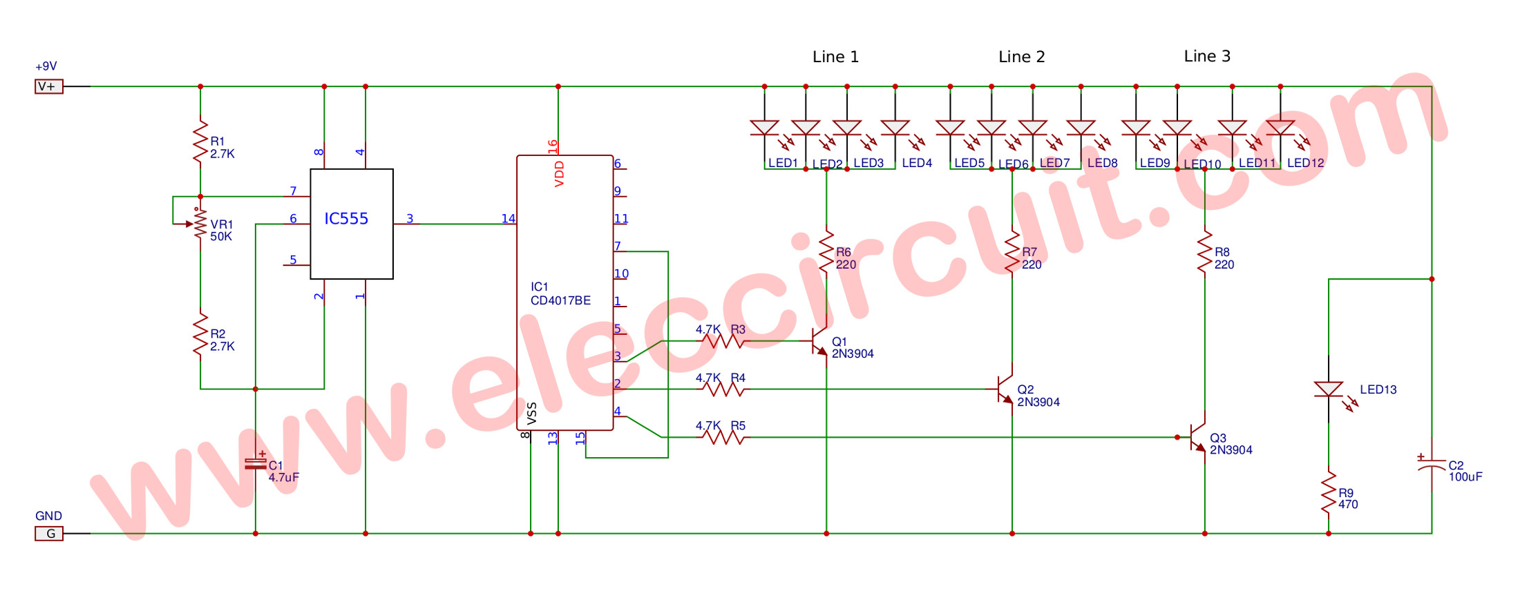
The only thing that confuses me is the constant reference to 555 oscillators in this thread. The 555 is a timing device that's very often used in situations where you want a running sequence of lights. I suspect a lot of real Star Trek hand props used exactly the sort of 555/4017 combinations that are being proposed here - the tricorders, etc - if they didn't do it with micros.

The thing is, you don't want a constant running sequence, you want a sequence that steps up or down when you press a button. That being the case, you don't need something that has a 555 in it. Just connecting a pushutton (via suitable debouncing circuitry) to the clock input of the 4017 will make it step up once every time you hit the button, which is sort of half of what you probably want. As we discussed before, there are imperfections with this simple approach. It won't count down, it'll only light one LED at once, and when you reach the top end it'll cycle around back to zero again. But that's sort of partly what you're after - and it doesn't need a 555 oscillator section.

You could theoretically build a 555 one-shot, but you might as well just connect it directly to the pushbutton. There wouldn't be a lot of point, other than perhaps as a really overcomplicated approach to debouncing.

What ICs do you have at hand?

HF

PS - Something else that strikes me is that many digital logic ICs aren't going to have the grunt to control, say, ten LEDs all at once. That's a not-insignificant amount of current. If things start getting hot, we may need to address this. Be aware.
 
Last edited:
Because of this, I steered away from the logic path when I wanted to do the Phaser Rifle many years ago. It would include a lot of wiring and hair pulling (because all it takes is one broken wire....). even if I did get it working, the circuit board will be very very large and not to forget, the amount of power it needs.

As I continue from my earlier post (page 1), I forgot to mention that this circuit I did was using 3 volts and I actually tapped the power from the toy's existing batteries after a few minutes probing it. But if you're using more than 5 volts, you will definitely need a 7805 voltage regulator, current limiting resistors and what-nots.

I have just drawn the circuit (from memory) this morning. As its using 3 volts, I did away with a lot more components since they're not that 'critical'. Based on my own experience, doing the circuit and also wiring it up is the easy part for me. What really took so long was learning how to program the $&@# chip by myself as I do not have friends who have the software nor the programmer. I am still learning until now as I really hate programming.

The programming was originally meant for the First Contact Phaser rifle which failed to materialise as no one wanted to put in the money for it. In this Phaser project, I modified the code from 16 LEDs to 10.

In theory, both circuits (LED & Playmates sound) are supposed to work together but during multiple firing, it does not. Still my friend, Peter, was happy with it. As far as the Phaser is concerned, I think its still working as my trigger-happy friend did not call me since 2010 :lol
 
This thread is more than 12 years old.

Your message may be considered spam for the following reasons:

  1. This thread hasn't been active in some time. A new post in this thread might not contribute constructively to this discussion after so long.
If you wish to reply despite these issues, check the box below before replying.
Be aware that malicious compliance may result in more severe penalties.
Back
Top